Antenna Recommendations for UAS and UGVs
Introduction
Antennas play an important role to get the maximum performance from the Doodle Labs radios. This document provides general antenna recommendations for UAS and UGV use cases.
Antenna Considerations
Some of the important things to consider when selecting an antenna are
- Center Frequency, Bandwidth, VSWR, Impedance
- Antenna Gain, Radiation Pattern and Beam Width
- Polarization (single or double)
- Type of antenna, material, choice of ground plane
Center Frequency, Bandwidth and VSWR
- Choose an antenna with the correct operating frequency and bandwidth and with a good VSWR. Do not choose a multiband antenna if you don't need one. Multiband antennas often perform significantly worse than single-band antennas for any one particular band.
- Choose an antenna whose bandwidth is wider than the requirement. This makes the antenna less susceptible to de-tuning.
- Doodle Labs Radios are designed to work with 50 Ohm impedance for best matching. There can be a big impedance variation even in the antennas that are specified for 50 Ohms. So choose a good quality antenna with a VSWR less than 2. Avoid using the 75-ohm impedance (TV antennas for example).
Antenna Gain, Radiation Pattern and Beam Width
In the same way that sound can be focused using a megaphone, RF waves can be focused by antennas. The antenna gain is the amount of amplification of the signal relative to an isotropic antenna (equal radiation in all directions). The radiation pattern describes the direction in which the RF waves are focused. The beam width describes the angle over which the radio waves are focused within 3 dB of the peak gain.
Choosing an appropriate antenna gain requires a link-budget calculation. Based on the network capacity and link distance required, you can calculate the required antenna gain. Also note that there are many factors which can affect RF propagation loss such as reflections off large objects, and Fresnel Zone clearance. Have a look the Application Note, Optimizing the RF Link in our Technical Library.
Some antennas like the patch antenna, and the parabolic dish antenna focus RF waves in a cone shape and can provide very high antenna gain. Such antennas need to be pointed towards the intended target. High gain omni-directional antennas focus RF waves in a horizontal plane like a pancake, and offer much less gain in the vertical direction. Note that sometimes the nulls in the radiation pattern are more useful than the peaks.
The figure below illustrates several of the concepts discussed above. As the UAV is flying over a source of noise, the null in it's antenna's radiation pattern is pointed towards the ground. A high-gain patch antenna is used on the GCS and pointed towards the UAV.
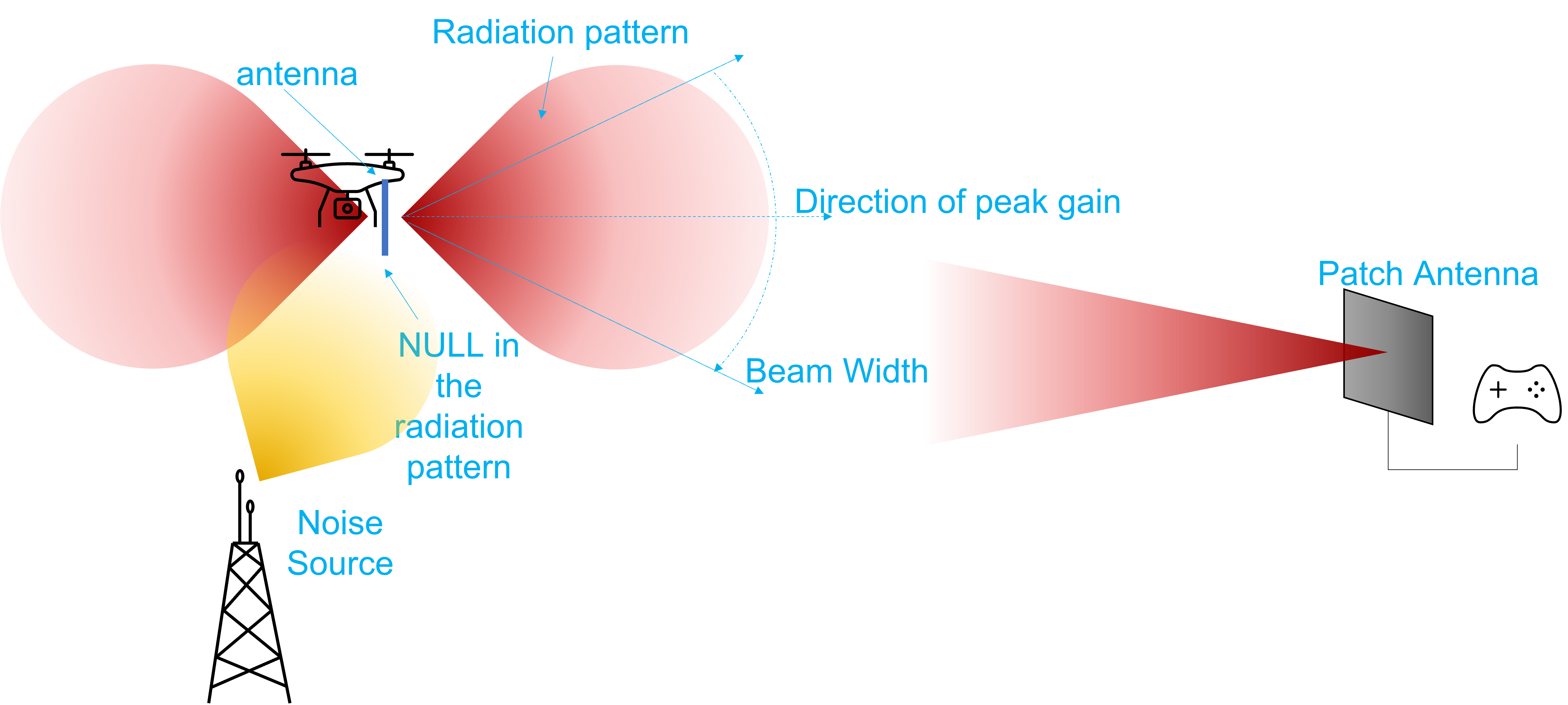
Pointing the antenna null towards the ground
Polarization
Antennas are either linearly polarized (horizontal, or vertical), or circularly polarized (CP). The polarization refers to the physical orientation of the RF waves, and antennas which are polarized vertically cannot receive horizontally polarized RF waves. The polarization of an RF wave can change as it reflects off of the ground or objects. In a UAS, the antennas tilt when the UAS banks, and this can cause some polarization mismatch. In order to guarantee reception, mount the antennas with both polarizations covered. However, note that this will make it difficult to point the antenna nulls towards the ground.
CP antennas can be right-hand or left-hand circularly polarized. RHCP antennas cannot receive LHCP RF waves. CP antennas receive linearly polarized RF waves with a 3-dB penalty.
Near and Far field
The near field of an antenna is a region physically close to the antenna. Objects inside the region can modify the radiating characteristics such as the VSWR and radiation pattern of the antenna. In the far field, the electromagnetic waves have detached themselves from the antenna, and therefore, objects in the far field can redirect or even absorb the waves, but cannot modify the radiating characteristics of the antenna.
In order not to degrade an antenna's performance, you should keep anything (especially conductive materials) outside of the near field of the antennas. You can refer to online calculators to calculate the near field distance of your antenna, but for typical low-gain omni-directional antennas, it is approximately half of a wavelength. At 915-MHz, this is roughly 16.4 cm.
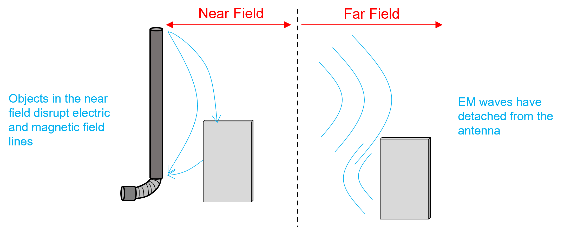
Near field and far field
Some antennas use a radome with a high dielectric constant which reduces the wavelength and therefore the near-field distance inside the radome. Such antennas are less affected by objects in close proximity.
Antenna Seletion and Mounting
Selecting Antennas
The choice of the correct antennas for UAS is a critical factor in determining the overall link performance. Typically the UAS is moving and regularly changing it's orientation. RF propagation over ground can be significantly more chaotic than a LOS connection to a UAS. At ground-level, it is very difficult to keep the Fresnel Zone of the RF propagation path clear of obstacles (including the ground). Furthermore, buildings and other large objects reflect and scatter EM waves causing multipath fading.
As a result, omni-directional antennas are usually used on the UAS/UGV. Size and weight are other important criteria for UAS. Hence small 2-3 dBi Dipole or Monopole antennas are used. Monopole antennas can be very small but keep in mind that they must be mounted on a ground plane.
Typically the GCS is in a fixed location, and it is possible to use larger and higher gain antennas to increase the range. 6 dBi Omni antennas are good for short to medium range operation. For long range links, directional antennas can provide a good solution and for very long range links, tracking dish antennas can be considered.
Mounting Considerations
Because of the high mobility of the UAS/UGV, mounting the antennas is a very important consideration.
- Use 2x2 MIMO antennas to get better diversity from the moving vehicle.
- Ideally the antennas should be mounted more than ½-wavelength apart so that they do not modify each other's radiation pattern. For example, at 915 MHz, the wavelength is 32.8 cm (12.9 inches). So the antennas should be at least 16.4 cm (6.4 inches) apart.
- Often the body of a UAS is made of carbon fiber which is weakly conductive. The body of the UAS can block/reflect RF waves, and may even modify the radiation pattern of the antenna.
- Choosing an antenna with a high dielectric constant radome may help to avoid near-field incursion, but more separation is better for antenna diversity.
- Depending on the application, the antennas should either be mounted in a V-shape for diversity or both mounted vertically in order to point the null towards any potential noise source.
- Care should be taken to ensure that the UAS is always within the GCS antenna's beam width. This is especially important when using high-gain antennas.
- We recommend testing the antenna mounting by moving the UAS/UGV 10-20 meters away and then rotating it while observing the RSSI value from the radio.
Recommended Antennas
When choosing antennas, choose a reputable manufacturer, and avoid low cost antennas, or antennas which do not have a full list of specifications. If the antenna is very small (smaller than ½ a wavelength), then you should be skeptical of its performance.
Ideally the antenna datasheet should include radiation patterns so that you can verify its uniformity. If the radiation pattern isn't shown the manufacturer may simply indicate the peak antenna gain, and that may not be useful in a real world deployment. The VSWR should ideally be less than 2:1.
The saying "you get what you pay for" is particularly true for antennas.
Doodle Labs Antennas
Doodle Labs offers antennas which are optimized for use with Doodle Labs radios for various frequency bands. These antennas are included in the radio Evaluation kit and available for volume purchase. Please visit the antennas section of our website for full datasheets.
Recommended Antenna Manufacturers
Due to the large variety of the antenna types, here we list a few antenna companies that our customers have reported good performance from.