Hardware Integration Guidelines
Power Supply Integration
Various Mesh Rider Radio models have different power supply ratings. See the datasheet for your Mesh Rider Radio model for more information.
A poorly designed power supply can cripple any system. Fig. 1 illustrates some recommendations worth noting when designing your power supply.
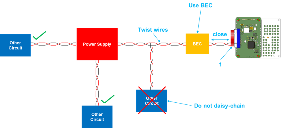
Fig. 1 - Power Supply Recommendations
In addition
- Choose a wire gauge that can support the maximum current draw.
- Recommended AWG ratings are available here: https://www.powerstream.com/Wire_Size.htm
- AWG 26 can handle 2.2 A for chassis wiring.
- Keep wires short and twist them for good EMI/EMC.
- Be careful running very long wires to any system. These act as big inductors which can create large transient voltage swings (even negative swings) on the supply lines, potentially damaging sensitive circuitry.
- Do not daisy-chain systems as this will cause power supply noise to couple between them.
- When debugging power supply issues, measure the voltage at location (1) in Fig. 2 (i.e. as close as possible to the Helixradio). Ideally this should be measured with an oscilloscope.
- Ensure that the power supply ripple is less than 100mW.
- Measure the voltage while transmitting at the highest possible power.
- A Battery Elimination Circuit (BEC) can ensure a stable supply. It is essentially a Buck Converter.
- Make sure that the BEC has a maximum current output higher than the radio’s maximum current draw.
- Keep the BEC close to the radio.
Thermal Management
In all Mesh Rider Radio models, most of the heat is generated by the RF Front End. We recommend attaching the largest flat metal surface of the RF Front End to a suitable heat sink. If your system chassis is thermally conductive, it can also be used as a heat sink. For good thermal coupling between the Mesh Rider Radio and your heat sink, you can use thermally conductive paste, or tape.
Ethernet Wiring
- It is not necessary to route the GND wire along with the Ethernet data wires.
- Ethernet signals are differential, and the +ve and -ve wires can be interchanged without any loss in functionality
- Most Ethernet transceivers use auto MDI-X which makes the RX and TX wires interchangeable.
- The Mesh Rider Radio uses on-board common-mode filters for EMC, but magnetics are not used. For short chassis wiring, it is usually not necessary to add magnetics or shielding, however they may be required in some applications. Magnetics are also used when very strong electrical isolation is required (some standards require over 1kV of isolation)
USB Wiring
- USB lines are sensitive to common-mode disturbances. Make sure to route GND with the +ve and -ve USB lines and twist all three lines together.
- USB +ve and -ve lines are not interchangeable.
Regulatory
- For ISM-band Mesh Rider Radios, the equipment label should have a note “Contains FCC ID: xxxxxxxx”. Many Doodle Labs radio models have gone through regulatory certifications. This is an ongoing activity so please inquire about the specific certification status of the model # used in your project.