Wearable Mesh Rider Radio - Hardware Integration Guide
Introduction
This Hardware Integration Guide provides the information to facilitate smooth integration and use of Wearable Mesh Rider Radio.
The Wearable Mesh Rider Radio is a small mesh radio, available in many frequency bands for deploying Private Wireless Networks. It includes a WiFi radio to create a mobile hotspot for team collaboration activities using standard mobile devices. For ease of use it integrates the Mesh Rider and WiFi antennas. It includes RM-SMA connectors for external antennas to increase the Mesh Rider's operating range.
Hardware Description
Figure 1 shows a diagram of the Wearable Mesh Rider Radio.
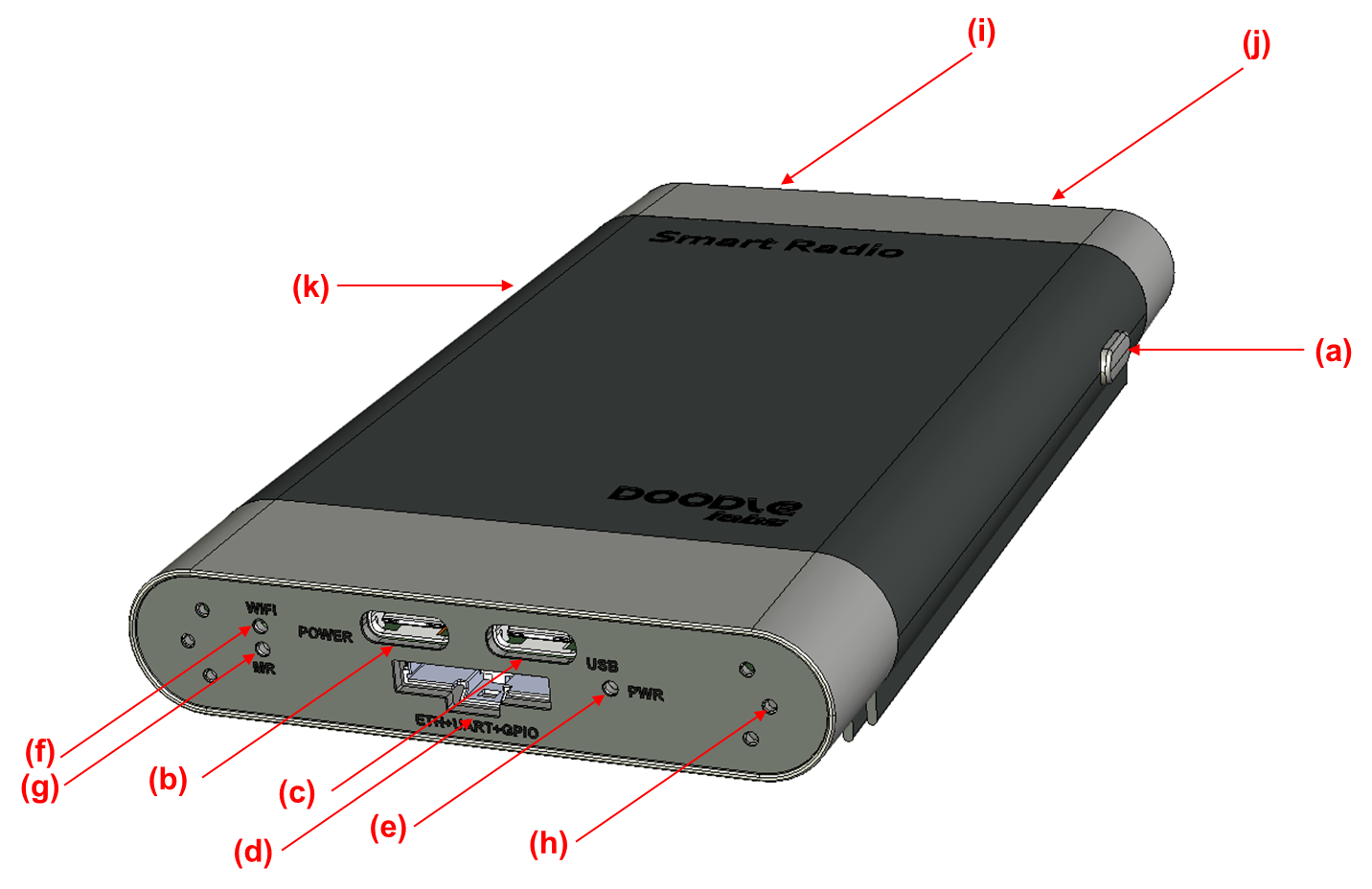
Fig. 1 Wearable Mesh Rider Radio Overview
a. Power Button
b. Power input 6-24 V (USB-PD Compliant)
c. USB DATA
d. Auxiliary port (USB Host, Ethernet, UART, GPIO) (Available on Xtreme category of models)
e. Power Indicator
f. WiFi Association Indicator
g. Mesh Rider Association Indicator
h. Peelable outer sticker
i. Antenna 0 (remove outer sticker) - (Available on Xtreme category of models)
j. Antenna 1 (remove outer sticker) - (Available on Xtreme category of models)
k. GPS SMA connector (remove cap) - (Available on Xtreme category of models)
Standard Interfaces
Fig 2 shows Mesh Rider Radio - Wearable’s electrical interfaces as shipped from the factory. These interfaces support the most common use-cases.
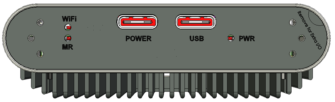
Fig. 2 Front panel with top label
The POWER port supports a 6-24V input voltage range. It can connect to USB-PD compliant battery packs, or normal power source inputs like batteries and DC voltages. The Mesh Rider Radio Power port does not include Galvanic Isolation. See the model-specific datasheet for details on power supply requirements.
The USB port is a USB device port and supports Ethernet over USB. Fig. 3 shows the Power Button State diagram.
- ON - The device is fully functional
- Standby - The OS is up, but the wireless subsystem is powered down
- Reset - The unit is rebooting
- Factory Reset - The unit reverts to it's factory default configuration and reboots
The power button is connected to the Power_ON pin on the Auxiliary connector. The Power_ON pin is internally pulled high, and can be actioned if it is pulled to GND. A state diagram of the Power_ON pin is shown in Fig. 3. A quick double-press occurs when two presses of less than 600ms at least 100ms apart and less than 900ms are performed.
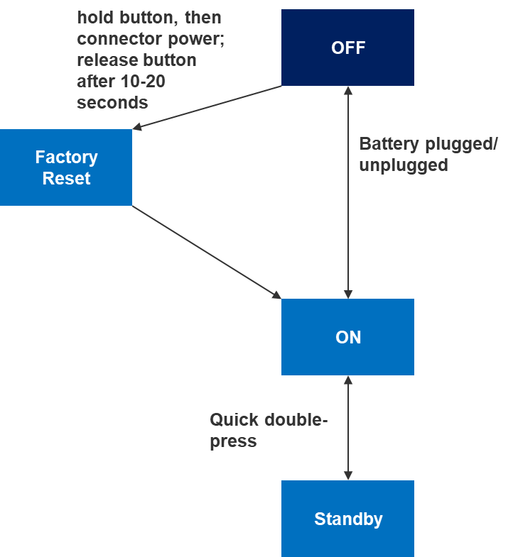
Fig. 3 Power Button State Diagram
Table 1: LED Behavior
| Condition PWR | LED | WIFI LED | MR LED |
|---|---|---|---|
| Booting Up | Flashing | Flashing | Flashing |
| ON, WiFi not associated, MR not associated | Steady | Off | Off |
| ON, WiFi associated, MR associated | Steady | Steady | Steady |
| Factory Reset | Fast Blink | Fast Blink | Fast Blink |
| Standby Mode | Off ↔ High Luminosity, breathing effect | Off | Off |
Additional Interfaces (Xtreme Category)
For special uses-cases, the Mesh Rider Radio - Wearable has additional interfaces. By removing the top label, additional interfaces will be revealed.
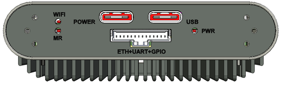
Fig. 4 Front panel after top label removed
The additional interfaces are:
- USB-Host port
- UART
- ETH1 (100baseT)
- GPIO1
- Power_ON pin
The Power_ON pin has an internal pull-up resistor and if pulled to ground by the user, it behaves the same way as if the Power push button were depressed.
Internal/External Antennas
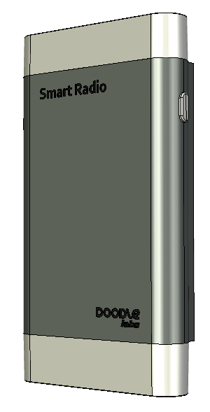
Fig. 5 shows the top panel as shipped from the factory. The default is to use embedded antennas for the Mesh Rider waveform.
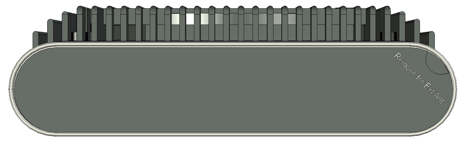
Fig. 5 Top panel (Embedded Antennas)
If you plan on attaching external antennas, remove the outer most labels on the top panel of the Wearable Mesh Rider Radio. Two SMA connectors will be exposed for antenna or cable attachments. Make sure to update the software configuration to use External Antennas. Details are in the Configuration Guide. In Fig. 6, the top-panel label is removed to reveal the SMA connectors for external antennas to extend the range of Mesh Rider.
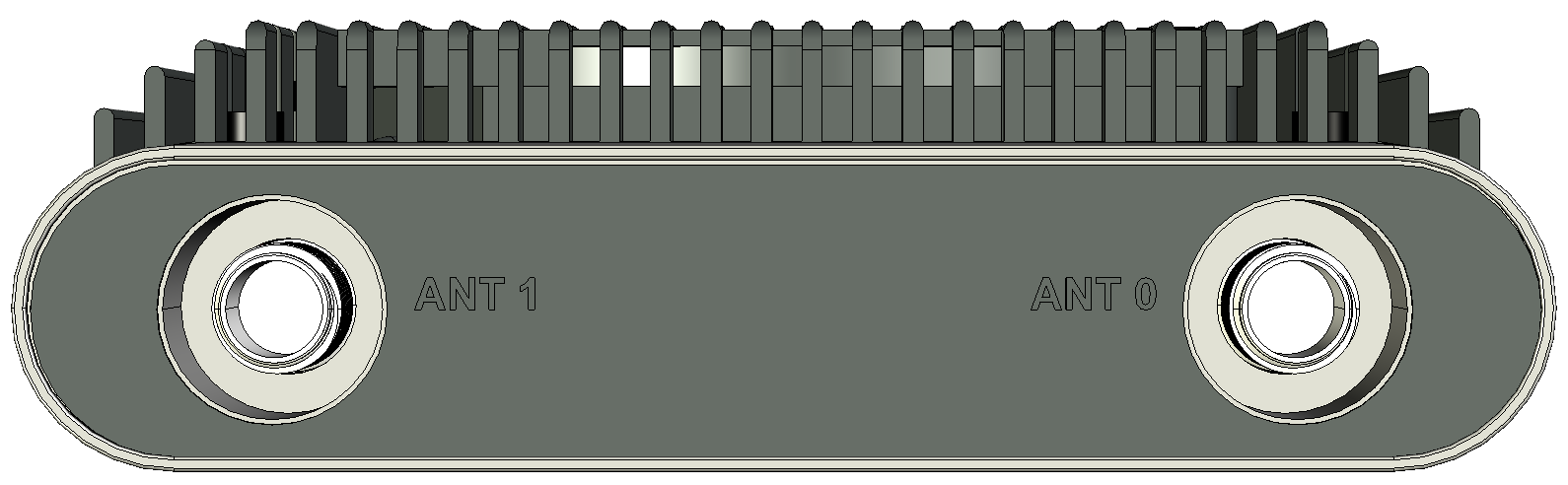
Fig. 6 Top panel with label removed.
The RF ports of the Mesh Rider Radio use SMA Female connectors. Any antenna with desired gain, directivity, and 50-ohm impedance will be compatible. RF ports include a protection circuit, so even in case of an open connection the Mesh Rider Radio will not be damaged.
Integrated GPS
The Mesh Rider Radio Wearable has an integrated GPS. The GPS includes an internal antenna, but if desired, you can connect your own external antenna using the GPS SMA port. This is configurable in software, and in order to reveal the GPS SMA connector, first release the screw at position (b), and then remove the cap using a pin at position (a) in the diagram below.
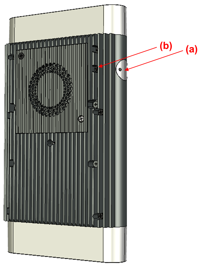
Fig. 7 External GPS Antenna Port
Additional Guidelines
The mini-OEM Mesh Rider Radio does not include galvanic isolation.
Additional hardware Integration Guidelines can be be found on our Hardware Integration Guidelines page.