Serial Interface Guide
The Mesh Rider Radio runs a customized version of Openwrt with enhancements related to the Doodle Labs Mesh Rider® technology. These enhancements are useful for applications requiring low-latency command-and-control transmission and high-throughput video - e.g. UAV and robotics.
The purpose of this guide is to aide a programmer in configuring the Mesh Rider Radio Serial interface. Communications over the Mesh Rider Radio's wireless interface are IP based, so it is necessary to relay packets from the network to the serial interface. This guide includes examples of how to send data from the serial interface of one radio to that of another radio, or to simply send packets directly over the network to the serial interface.
Hardware Setup
Doodle Labs currently offers four main hardware variants in its Mesh Rider Radio lineup. UART is available on all hardware variants. However, these hardware variants have different pinouts and you should refer to the documentation package of your specific hardware for pinout information. The hardware versions can be differentiated by the model number. In all cases, the UART is implemented as one TX line, one RX line, and GND.
Please note that - 1. The legacy models (-2H-*U) have a USB host port on the auxiliary connector and have no UART port. For the UART port, you require -2H-*S model.
Connection Guide
- The UART connector is a 3-pin connector consisting of TX, RX, and GND. The TX and RX wires should be coupled closely with the GND wire for good signal integrity.
- Typically, when two devices are connected over UART, the TX wire of the first device should be connected to the RX wire of the other device and vice versa.
- While most models use 3.3-V TTL signaling, the External Mesh Rider Radio (-2J-*E) uses RS232 signaling. Please consult the documentation package of your hardware before hooking up the UART.
Serial Interface Configuration
Start with one of the hardware setups in the section above. A generic setup is shown in Figure 1.
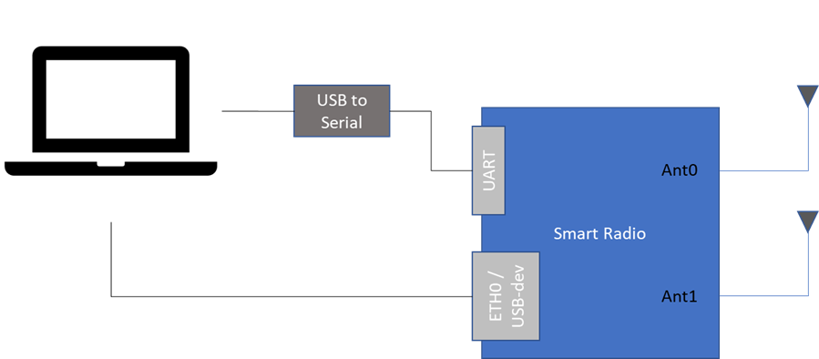
Fig. 1 Generic UART hardware connection
Configuring the UART port using the GUI
The GUI is strictly for configuring the UART port as a Serial to Network bridge. Open up a web browser and navigate to the IP address of the Mesh Rider Radio. From there, navigate to Services -> Serial Configuration. A screenshot of the GUI is shown in Fig. 2. For mobile applications, we recommend using UDP transport over TCP transport as it is more responsive.
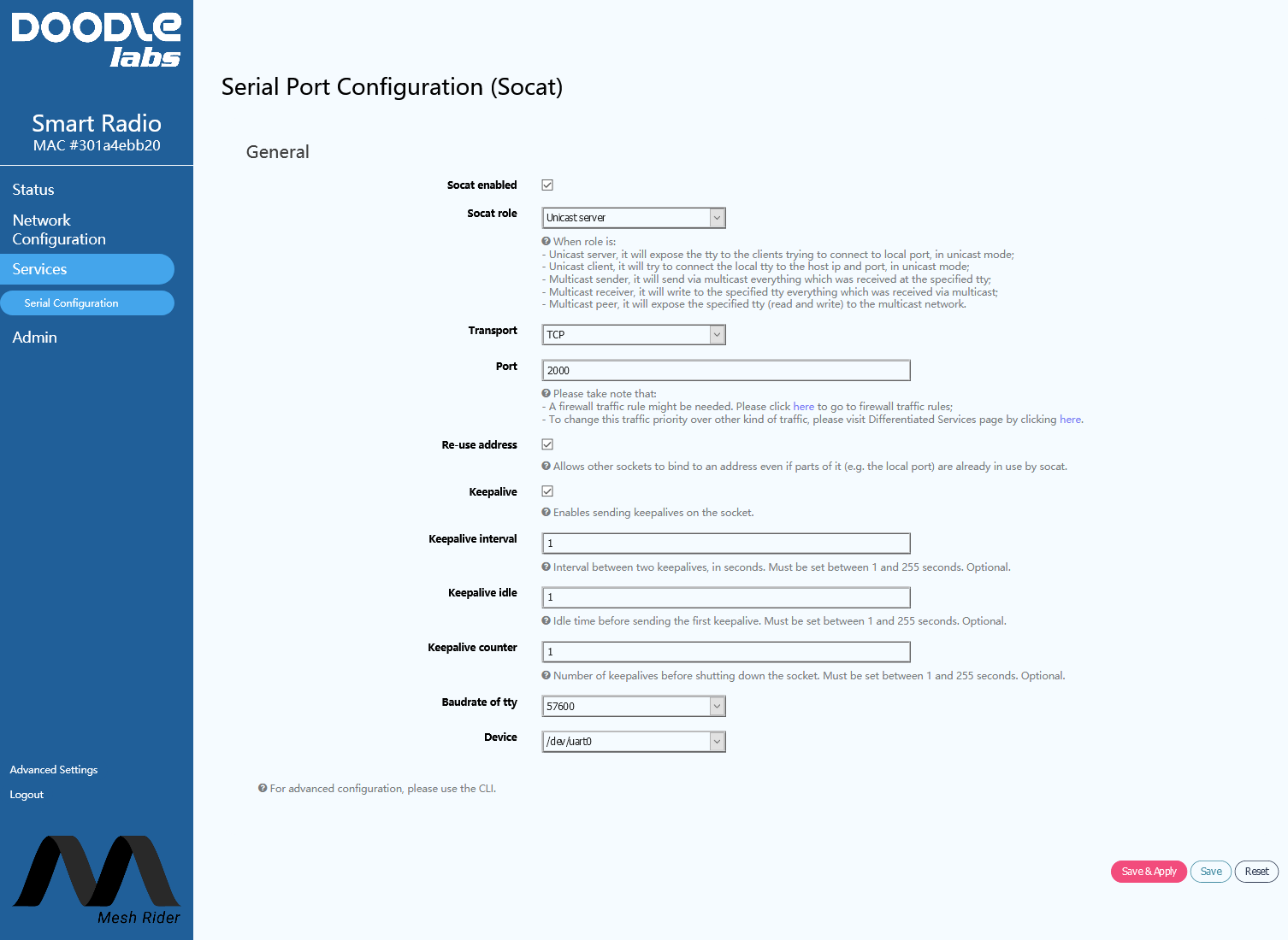
Fig. 2 UART Configuration GUI
When configuring the serial to network relay using the GUI, the program, socat, is used in the background. For unicast traffic, the relay should operate as either a server which listens on a particular network port for incoming connections, or a client which attempts to connect to a particular IP address and network port. For multicast traffic, the relay can either send, receive, or operate bi-directionally. It will be necessary to open the firewall at the desired network port, and a link to the firewall page is provided. For multicast traffic, it is also necessary to update the routing table and a link is provided to the static route page. An example static route is shown in Figure 3.
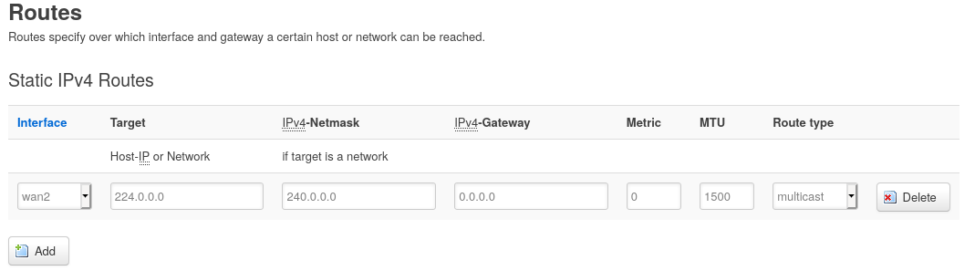
Fig. 3 Static route configuration for multicast traffic
Choose the device /dev/uart0. After making your changes, click Save & Apply. If you are familiar with Socat and want to use your own arguments, then you can input them using the checkbox at the bottom of the page.
The remainder of this section discusses configuration using the CLI.
GCS Network Port Binding (Important)
Some GCS software (notably Mission Planner) do not allow the user to bind the socket to a particular network port when in client mode. Instead, the network port is assigned by the kernel. Therefore, every time Mission Planner restarts it's UDP client, it will restart from a new network port. Unfortunately, this confuses socat (on the Mesh Rider Radio), and it can lead to high MAVLink packet loss.
The suggested solution is to setup socat in client mode and input the IP address of the GCS. In that case Mission Planner will be in UDP server mode and listening on port 14550. Alternatively, you can use the GCS Finder utility described later in this document.
Manual Configuration and Debugging the UART port
We recommend using the GUI for serial port configuration, but if you want an advanced configuration, then you may also use the CLI. This guide is not designed to be comprehensive, and if you plan on using the UART port manually, then you will need to have Linux expertise. We will discuss some of the tools which are built into the Mesh Rider Radio for you to use, and this section will also be useful as a debugging guide.
You can SSH into the radio by running
user@host-pc:~$ ssh root@<IP Address>
It may be necessary to update your PC's list of known hosts first.
user@host-pc:~$ ssh-keygen -R <IP Address>
The UART interface is attached to /dev/uart0.
Disable Socat
Before attempting to use the UART port manually, ensure that socat is disabled. SSH into the radio and run
root@smartradio:~# uci set socat.http.enable='0'
root@smartradio:~# uci commit
root@smartradio:~# /etc/init.d/socat restart
This can also be done in the web GUI.
STTY Configuration
The default UART settings can be changed using the stty program which is installed on the Mesh Rider Radio. An example usage is,
root@smartradio:~# stty -F /dev/ttyUSB0 115200 cs8 -cstopb -parenb
which sets the speed to 115,200 baud, 8 data bits, 1 stop bit and no parity.
(Please note that the Helix Mesh Rider Radio's UART port supports max 115,200 baud).
picocom
From the May 2021 firmware release onwards, picocom is installed by default on the Mesh Rider Radio. picocom is a terminal access program which can be used for general debugging of the UART port. You can invoke picocom with
root@smartradio:~# picocom -b 115200 /dev/uart0
You can exit picocom by holding down CTRL, and the hitting a and then x. For a full list of commands, just type picocom.
cat and echo
A single message can easily be sent on the UART port using echo
root@smartradio:~# echo -ne "Hello World\n" > /dev/ttyUSB0
or received on the UART port using cat
root@smartradio:~# cat < /dev/ttyUSB0
These programs use the settings applied by stty as defaults.
agetty
The program agetty can be used to open a serial console over the USB UART port. First access the Mesh Rider Radio over SSH, and then run
root@smartradio:~# agetty -8 115200 ttyUSB0 -n -l /bin/ash
socat and ser2net
socat and ser2net are installed on the Mesh Rider Radio, however, due to a socat bug, we strongly recommend that you use the web GUI for their configuration.
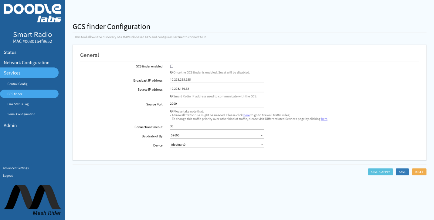
GCS Finder
If you are using a MAVLink-based Ground Control Station (GCS) such as QGroundControl or Mission Planner, you can use our built-in GCS-Finder utility. The connection diagram is assumed to be like that in Fig. 4.
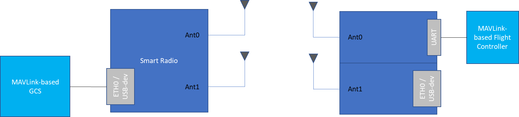
Fig. 4 UAV GCS System
The GCS-Finder uses broadcast packets to search for MAVLink-based GCS which are listening for UDP packets on port 14550. The default behavior can be modified by navigating to services -> GCS finder in the web GUI. A screenshot is shown in Fig. 5. After enabling GCS Finder, socat will be disabled automatically.