Low Latency C&C and Video Streaming with the Nvidia Jetson Nano
Introduction
This document is a basic tutorial for how to get started with the Doodle Labs Mesh Rider Radio and the Nvidia Jetson Nano in a video streaming application. Additionally, we demonstrate how the Mesh Rider Radio con be configured to optimize a Command and Control while streaming video at the same time. The Nvidia Jetson Nano is a popular System-on-Module (SOM) used for emerging IoT applications such as drones, robots, and generally devices which can make use of its powerful AI capabilities. It includes a GPU which can perform fast H.264/H.265 video encoding and decoding making it ideal for low latency video streaming. This tutorial is divided into the following sections:
- Video System Block Diagram
- Hardware Setup
- First Time Jetson Nano Setup
- Mesh Rider Radio Configuration
- Preparing GStreamer
- Video streaming and Command and Control
- Advanced Video Streaming
This tutorial makes use of the gstreamer command-line tools, gst-launch-1.0 and gst-inspect-1.0. Building a C-application is beyond the scope of the tutorial.
The latency added by the Mesh Rider Radio network is less than 10ms for both concurrent HD video and the C&C data.
Video System Block Diagram
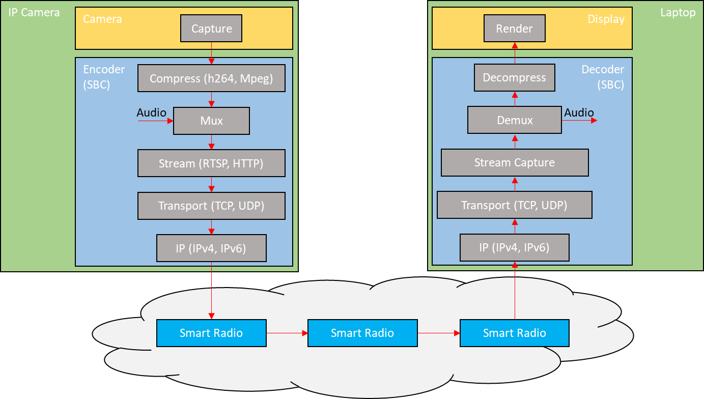
Fig. 1 Video Data Flow
The block diagram above illustrates the data flow path of a simple streaming application. The cloud of Mesh Rider Radios represents a mesh situation where the video feed may hop across a node before arriving at the destination Mesh Rider Radio. For a discussion of the different blocks , please see the document, "Mesh Rider Radio Video Streaming Tutorial".
Hardware Setup
This tutorial makes use of the Nvidia Jetson Nano Developer Kit which has standard interfaces like USB, HDMI etc. Basic hardware setup for streaming is shown below.
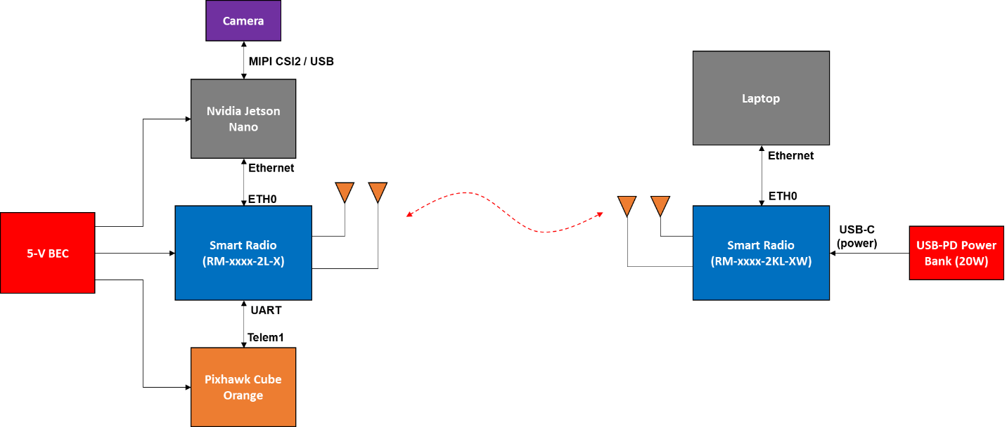
Fig. 2 Basic Hardware Setup
Power
The Jetson Nano can be powered over the standard USB Micro device port (J28) or the barrel connector (J25). Use a 5-V supply with at least a 2-A current rating. The camera is powered over the MIPI CSI2 or USB interface. Follow the datasheet of your particular Mesh Rider Radio model when choosing a power supply.
Camera Setup
You may use the MIPI CSI2 interface, or a USB interface. USB 2.0 has a maximum link speed of 480 Mbps which is unsuitable for raw 1080p30 video, which means that you will either need a USB 3 interface, or you will need to transcode from MJPEG to H.264. Transcoding MJPEG to H264 adds about 100ms to the latency in our tests. The MIPI CSI2 interface is only suitable for short connections, and ideally it should be shielded against EMI. Note that the HDMI port on Nano is an output port, so you cannot connect an HDMI camera to it. A global shutter is preferred since a rolling shutter produces a wavy effect when the UAV is moving. Additionally, some cameras have some form of image stabilization (optical or electronic), which is useful on UAVs.
We tested the control loop using the Nvidia Jetson Nano with two different cameras [1][2].
- Raspberry Pi HQ Camera (imx477)
- E-Con Systems See3CAM_CU135 - 4k USB3.0 Camera (AR1335)
Mesh Rider Radio Setup
In Fig. 2, we are using the OEM Mini form-factor of the Mesh Rider Radio on the UAV side, and the Wearable form-factor on the GCS side. Refer to their respective integration guides for details on the connections. Regardless of the form-factor, all Mesh Rider Radios include an Ethernet interface which can be connected to the Jetson Nano on the UAV.
First Time Jetson Nano Setup
The first time you use the Jetson Nano, you may find it easier to get it setup using a monitor and keyboard. Hook up your monitor to the HDMI port, and keyboard/mouse to the USB ports.
Getting the Firmware
There are extensive guides available on the Nvidia website which detail how to prepare your Jetson Nano. The basic steps are:
- Download and extract the latest firmware image. In this tutorial, we used JP 4.4.
- Format your SD card and burn the firmware image to the SD card using a program such as Balena Etcher.
- Inset the SD card into the Jetson Nano, and power up.
The first time you boot up the Jetson Nano, you will be asked to setup a username and password, and these will be required for SSH or Serial access later. By default, the Jetson Nano is setup as a DHCP client. Therefore, you can connect it to your office router so that it can get an IP address and access the internet. Once you have connected to the internet, run
$ sudo apt update
$ sudo apt upgrade
This will make sure that your package lists and packages are up to date. After that make sure that your Jetson clock is synchronized. This is necessary to access secure websites.
$ timedatectl
                      Local time: Tue 2020-05-05 16:23:05 +08
                  Universal time: Tue 2020-05-05 08:23:05 UTC
                        RTC time: Tue 2020-05-05 08:23:06
                       Time zone: Asia/Singapore (+08, +0800)
       System clock synchronized: yes
systemd-timesyncd.service active: yes
                 RTC in local TZ: no
After the initial setup is complete, connect the Jetson Nano to the Mesh Rider Radio as shown in the hardware diagram.
Mesh Rider Radio Configuration
In this section, we describe simple steps to setup the Mesh Rider Radio for video streaming. If you are not sure how to make any of these configuration settings, then please consult the Mesh Rider Radio Configuration Guide.
IP Configuration
The main requirement for the IP configuration is that all nodes in the network are on the same subnet and can therefore reach one another directly. You may choose to enable a DHCP server on the network, or just use static IP addresses. The Jetson Nano is pre-configured as a DHCP client. However, by default, the Mesh Rider Radio does not have the DHCP server enabled.
Enabling a DHCP Server
- In the GUI, navigate to
Network -> InterfacesandEDITthe WAN interface. - Change the protocol from
DHCP ClienttoStatic Addressand clickSwitch Protcol - We need to choose an IP address and Netmask for this node. In the screenshot below, we used
192.168.100.1as the static IP address and255.255.255.0as the netmask. - Scroll to the bottom and under the
DHCP Server section, deselectignore interface. The default settings are ok, so just clickSave & Apply. At this point you should make sure all nodes on the network are setup as DHCP clients. This is true by default for the Mesh Rider Radio which are DHCP clients, but also have a fixed IP address.
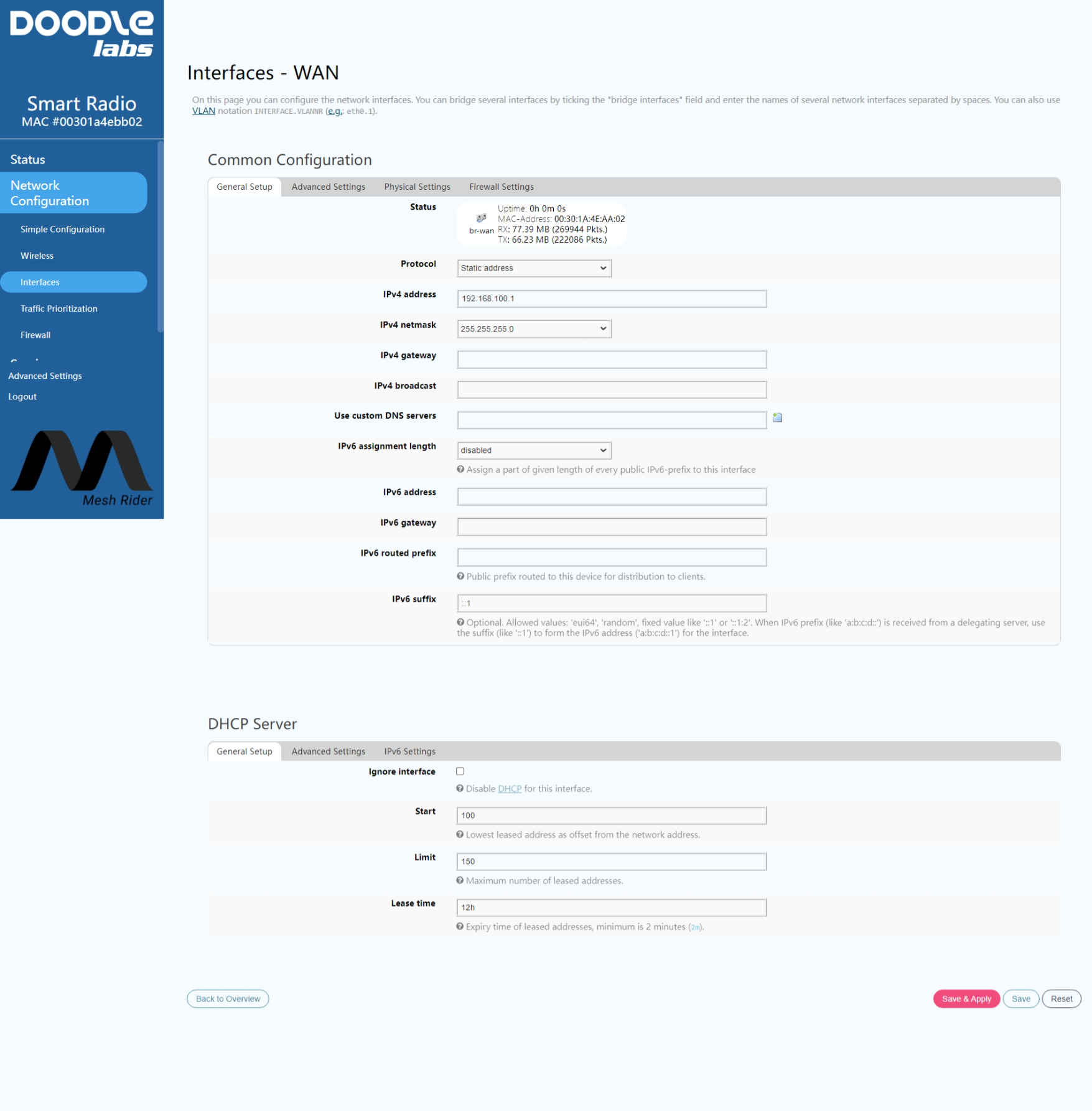
Fig. 3 DHCP Configuration
All nodes in the network should now have an IP address in the 192.168.100.0/24 subnet. You can find the IP addresses of all nodes on the network by logging into the Mesh Rider Radio over SSH and using the address resolution protocol. You can identify connected devices by their hardware address.
root@smartradio-301a4ebb02:~# arp
IP address       HW type     Flags       HW address            Mask     Device
192.168.100.210  0x1         0x2         b0:25:aa:2d:d3:8e     *        br-wan
192.168.100.185  0x1         0x2         00:30:1a:4e:aa:01     *        br-wan
192.168.100.193  0x1         0x2         00:30:1a:4e:aa:09     *        br-wan
Note that the above steps apply for both WDS AP/Client and Mesh modes.
Traffic Prioritization
Figure 4 shows the configuration menu for Differentiated Services. This page can be found by navigating to network -> Traffic Prioritization in the web GUI. Traffic optimization works by filtering packets based on their network port, IP address or transport layer protocol and placing them in one of four different queues - best effort, command/control and voice, video, and background. Doodle Labs Mesh Rider Radios include additional optimizations for video and command/control data which can be enabled by checking the relevant radio buttons in the Traffic Prioritization configuration menu.
The video bad link threshold is an additional failsafe where the video stream is guaranteed to be dropped if the signal strength is lower than the defined threshold. The default numbers make it disabled.
You may also enable Diversity Rates Only which limits the radio’s modulation rate to slower but more robust rates. This is recommended for highly dynamically changing channel conditions or UAV movement.
Lastly, make sure to create a rule for your RC/telemetry connection like the ones already defined. By default, port 14550 (MAVLink) is sent to the command and control queue. You do not need to create a rule for your video stream.
After making your changes, click Save & Apply.
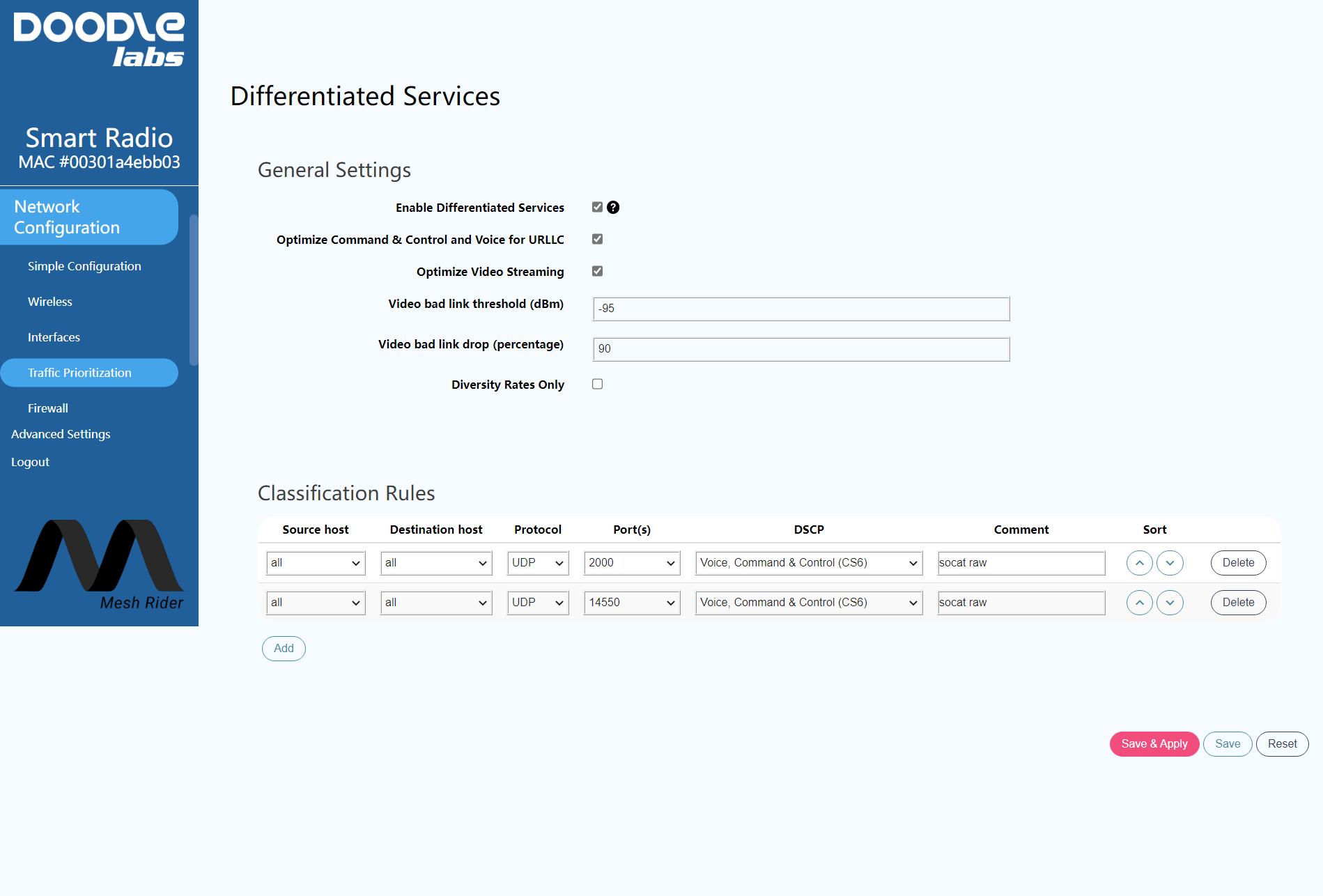
Fig. 4 Differentiated Services Configuration Menu
Preparing GStreamer
GStreamer is a framework for creating multimedia streaming applications and is available in multiple platforms including Windows, iOS, Android, and Linux [3]. GStreamer is installed in the Jetson Nano by default and you can write simple pipelines to steam video without any additional setup. This guide focuses on using RTSP streaming, which is commonly used for real-time streaming applications.
In order to stream using RTSP, you either need to write your own application, or use gst-rtsp-server [4]. gst-rtsp-server requires the gtk-doc-tools package to be installed.
$ sudo apt install gtk-doc-tools
In order to use gst-rtsp-server, you need to clone the repository, checkout the version of gst-rtsp-server suitable for your GStreamer version, and the build the application. Start by creating a working directory.
$ mkdir workingDir
$ cd workingDir
$ git clone https://github.com/GStreamer/gst-rtsp-server.git
$ cd gst-rtsp-server
$ gst-launch-1.0 --version
GStreamer 1.14.5
https://launchpad.net/distros/ubuntu/+source/gstreamer1.0
The version of GStreamer we have is 1.14.5, so checkout the corresponding git branch.
$ git checkout 1.14.5
$ ./autogen.sh
$ ./configure.sh
$ make
$ sudo make install
gst-rtsp-server is now ready to be used.
Video Streaming and Command and Control
Before starting a video stream, first get the information on your video camera’s capabilities. You can list the cameras attached to the Jetson Nano and check their capabilities using v4l2-ctl.
$ v4l2-ctl --list-devices
vi-output, imx219 6-0010 (platform:54080000.vi:0):
        /dev/video0
$ v4l2-ctl -d /dev/video0 --list-formats-ext
ioctl: VIDIOC_ENUM_FMT
        Index       : 0
        Type        : Video Capture
        Pixel Format: 'RG10'
        Name        : 10-bit Bayer RGRG/GBGB
                Size: Discrete 3264x2464
                        Interval: Discrete 0.048s (21.000 fps)
                Size: Discrete 3264x1848
                        Interval: Discrete 0.036s (28.000 fps)
                Size: Discrete 1920x1080
                        Interval: Discrete 0.033s (30.000 fps)
                Size: Discrete 1280x720
                        Interval: Discrete 0.017s (60.000 fps)
                Size: Discrete 1280x720
                        Interval: Discrete 0.017s (60.000 fps)
In our case, we have one camera which is attached and it is exposed to the user as /dev/video0. Our tests will be conducted using 1920x1080 at 30 fps. Fast encoding at H.264 can be accomplished using the omxh264enc plugin. You can see details and options of the omxh264enc plugin using
$ gst-inspect-1.0 omxh264enc
The output is very long and is not shown. The equivalent H.265 encoder plugin is omxh265enc. Nvidia has an Accelerated GStreamer User Guide available online which details some of the capabilities of the Jetson Nano when used with GStreamer.
RTP Streaming
Before diving into RTSP streaming, we can test a simple RTP video stream. In this case, the Nvidia Jetson Nano will act as the client, and it will directly stream video packets to a known listening server.
The RTP client can be started on the Jetson Nano using
$ gst-launch-1.0 nvarguscamerasrc ! "video/x-raw(memory:NVMM)",width=1920,height=1080,framerate=30/1,format=NV12 ! videoconvert ! omxh264enc control-rate=constant bitrate=5000000 iframeinterval=15 ! h264parse ! rtph264pay name=pay0 pt=96 config-interval=-1 ! udpsink host=<IP ADDRESS> port=5000 sync=false
where <IP Address> is the IP address of the receiving PC. The video feed can be picked up on the receiving PC with
$ gst-launch-1.0 -v udpsrc port=5000 caps='application/x-rtp, media=(string)video, clock-rate=(int)90000, encoding-name=(string)H264, framerate=(fraction)30/1, width=(string) 1920, height=(string) 1080, playload=(int)96' ! rtpjitterbuffer latency=100 ! rtph264depay ! avdec_h264 ! videoconvert ! autovideosink sync=false
All instances of h264 above also work with h265.
RTSP Streaming
RTSP streaming can be started using
$ ./gst-rtsp-server/examples/test-launch "nvarguscamerasrc ! video/x-raw(memory:NVMM) width=1920 height=1080 framerate=30/1 format=NV12 ! omxh264enc control-rate=constant bitrate=5000000 iframeinterval=15! h264parse ! rtph264pay name=pay0 pt=96 config-interval=-1"
Note that the command points to the gst-rtsp-server directory which was cloned earlier. The stream can be picked up on the receiving PC using
$ gst-launch-1.0 -v rtspsrc buffer-mode=0 do-retransmissions=0 drop-on-latency=1 latency=100 location=rtsp://<IP Address>:8554/test ! application/x-rtp, payload=96 ! rtph264depay ! avdec_h264 ! videoconvert ! autovideosink sync=false
where <IP Address> is the IP address of the Jetson Nano. All instances of h264 above also work with h265. In the command above we use UDP as the transport protocol. To use TCP, the location=rtsp:// part should be changed to location=rtspt://.
QGroundcontrol
Important Note: It is not possible to change the RTSP client settings in QGroundControl, and we have found that many of the default settings are not suitable for real-time video streaming. If you are using QGroundControl and are experiencing video issues, then we recommend avoiding RTSP, and using the simple RTP streaming discussed in the section above.
The RTSP stream can be picked up using QGroundcontrol with either H.264 or H.265 encoding. Figure 5 shows the relevant settings, and Fig. 6 shows a screenshot of the video feed with 2Mbps H.265 encoding. Note that QGroundcontrol does not support RTSP over TCP by default.
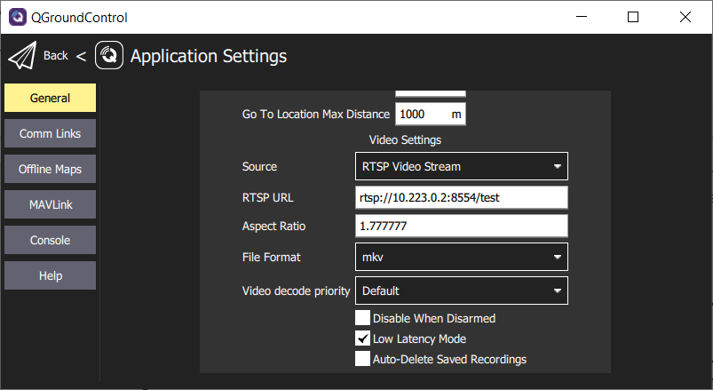
Fig. 5 QGroundcontrol RTSP settings
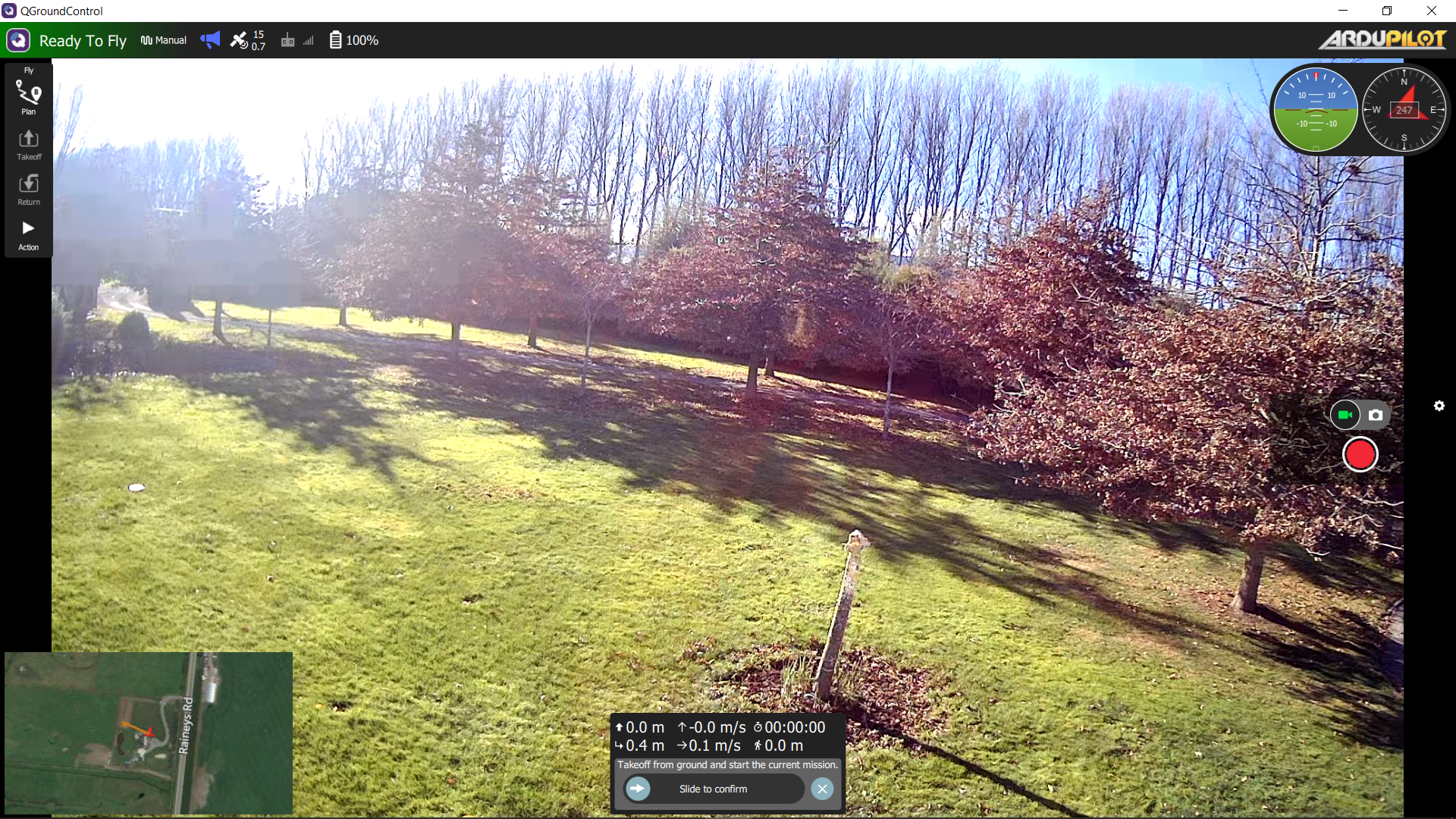
Fig 6 RTSP Stream in QGC 2Mbps H.265 Encoding
Results
With the above settings, we measured the glass-to-glass latency while running hping3 at the same time. hping3 is a Linux command-line utility which can be used to measure UDP latency (among other things). You can install and run hping3 by running
$ sudo apt install hping3
$ sudo hping3 --data 500 --destport 14550 10.223.0.2
HPING 10.223.0.2 (enp4s0 10.223.0.1): NO FLAGS are set, 40 headers + 500 data bytes
len=40 ip=10.223.0.2 ttl=64 DF id=43729 sport=14550 flags=RA seq=0 win=0 rtt=3.8 ms
With the above settings, the glass-to-glass latency was typically 110ms with only about 10ms for the transport through the Mesh Rider Radios. The difference between TCP and UDP was around 3 ms. Figure 7 shows the results.
Note that Doodle Labs Mesh Rider uses special radio and parameters to optimize the video transmission over wireless medium in high interference areas. For video transmission within Mesh Rider Radio private network, we recommend use of TCP. We can see that the latency added by the Mesh Rider Radio network amounted to less than around 10ms.
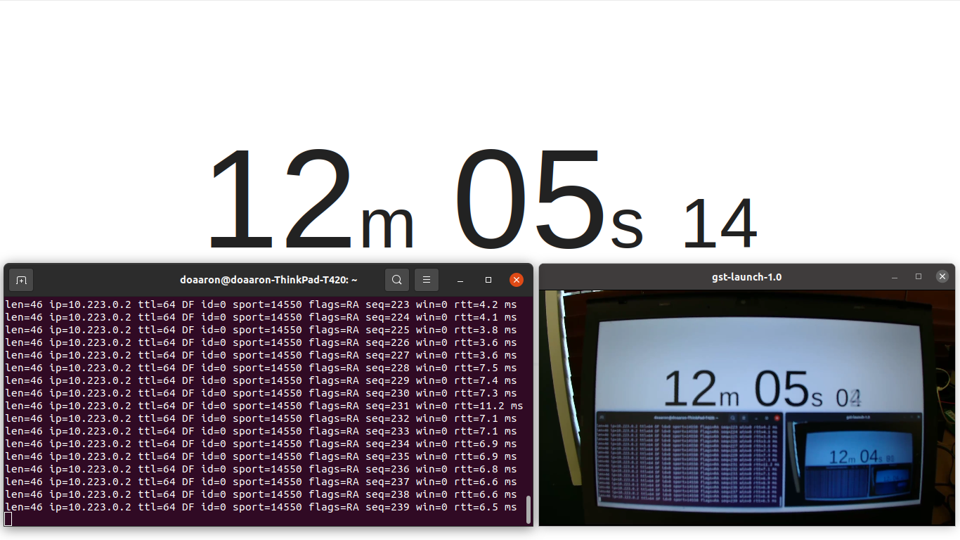
Fig. 7 Glass to glass latency
Advanced Video Streaming
In this section, we will cover some advanced video streaming protocols which can improve video performance in various adverse conditions. We present some example gstreamer pipelines as-is, but bear in mind that many of these may not be integrated into applications such as QGroundControl.
Pipeline Configuration
The RTSP pipelines which we used above can be tailored for different applications. Some of the settings which are useful to configure in highly dynamic applications (UAVs) are discussed below.
- Encoder Bitrate - The encoder bitrate controls the bandwidth used to send the video. Any wireless link has a limited network capacity, and if the bitrate exceeds this capacity, frames will be dropped.
-
Encoder i-frame interface - The i-frame interval determines how often key interval frames are sent. In H264/H265 encoding, image frames are compressed in image-space and time. I-frames, however, are not compressed in time. In contrast to i-frames, p-frames and b-frames require information from previous and future frames to be decoded, so if an i-frame is dropped, all subsequent frames until the next i-frame could be affected.
- We recommend keeping a very low i-frame interval for highly dynamic channel conditions. This will result in a general degradation in picture quality, but fewer frame drops.
-
Intra-refresh type - Some encoders allow you to divide i-frames into multiple sub-frames. Rather than encoding the entire i-frame at once, the frame is split into different regions, and the i-frame of each region is encoded at cyclically. Since i-frames are significantly larger than p/b-frames, this has the effect of making the bit-stream more stable which is easier on the radio link.
- Region-of-interest - Some encoders allow you too choose a region-of-interest within the frame. Usually is is a rectangle in the center of the frame, and it will be encoded at a higher resolution than the rest of the frame.
Forward-Error-Correction
Forward-Error-Correction (FEC) is an encoding method whereby data is sent redundantly so that missing or erroneous data can be recovered at the receiver. FEC is already used at the bit level by the radio, but it can be added at either the transport or application level. Gstreamer integrates the FEC encoder/decoder elements gstfeculpenc and gstfeculpdec [5][6].
An example RTP sending pipeline using the raspberry pi is
gst-launch-1.0 --gst-debug-level=3 rpicamsrc bitrate=2000000 exposure-mode=sports awb-mode=1 keyframe-interval=15 rotation=180 preview=false sensor-mode=5 ! video/x-h264,width1280,height=720,framerate=30/1 ! h264parse ! rtph264pay config-interval=-1 name=pay0 pt=96 ! rtpulpfecenc percentage=100 pt=122 ! udpsink host=10.223.0.1 port=5000
An example RTP receiving pipeline is
gst-launch-1.0 -v udpsrc port=5000 caps='application/x-rtp, media=(string)video, clock-rate=(int)90000, encoding-name=(string)H264, framerate=(fraction)30/1, width=(string)1920, height=(string)1080, playload=(int)96' ! rtpulpfecdec pt=122 ! rtph264depay ! avdec_h264 ! videoconvert ! autovideosink sync=false
MTU Sizing
The Maximum Transmission Unit (MTU) is the largest data packet that the network will support. Reducing the MTU size used by the video streaming application will result in smaller over-the-air packets. A smaller packet is in the air for a shorter duration and therefore is less likely to be corrupted. However, the MTU size also directly affects the network capacity. As each packet in a unicast transmission needs to be acknowledged, it is less efficient to send smaller packets and then wait for an acknowledgement.
In GStreamer, you can configure the MTU in an RTSP stream using the rtph264pay element. An example configuration would be
rtph264pay config-interval=-1 name=pay0 pt=96 mtu=250
Adaptive Bitrates
The network capacity is the throughput that the network can support at any particular time. In a UAV scenario, the network capacity can change throughout the mission. The most obvious case is where the UAV is flying away from the GCS, which results in a steady drop in the network capacity over time. Using dynamically adaptive bitrates to modify the video encoder’s bitrate based on the network capacity can result in a stable video feed even in harsh RF environments or at long range.
References
- Raspberry Pi HQ Camera, https://www.raspberrypi.com/products/raspberry-pi-high-quality-camera/, 18-8-2022
- E-Con Systems 4K USB Camera, https://www.e-consystems.com/4k-usb-camera.asp, 18-8-2022
- Gstreamer, https://gstreamer.freedesktop.org/, 18-8-2022
- gst-rtsp-server, https://github.com/GStreamer/gst-rtsp-server, 18-8-2022
- Gstreamer gstulpfecenc, https://gstreamer.freedesktop.org/documentation/rtp/rtpulpfecenc.html?gi-language=c, 26-7-2022
- Gstreeamer gstulpfecdec, https://gstreamer.freedesktop.org/documentation/rtp/rtpulpfecdec.html?gi-language=c, 26-7-2022