Mesh Rider Production Testing Guide
Introduction
This document discusses a recommended setup for production testing of the Mesh Rider radios in an end-product (e.g. a UAV and a GCS). Every interface (Ethernet, USB, Wireless etc) of all Mesh Rider radios are fully tested prior to the radios being shipped. However, it is still often a good idea to perform a final test of the radio's link inside the end-product before shipping out your product to your end customer. This should be a quick and easy go/no-go test to determine if there were any problems during the final integration such as electrical damage, or loose/damaged wiring.
For details on how to access the radio's command prompt or over it's other APIs, please see our Remote Management Guide.
Test Setup
Fig. 1 shows how you can set up your production test.
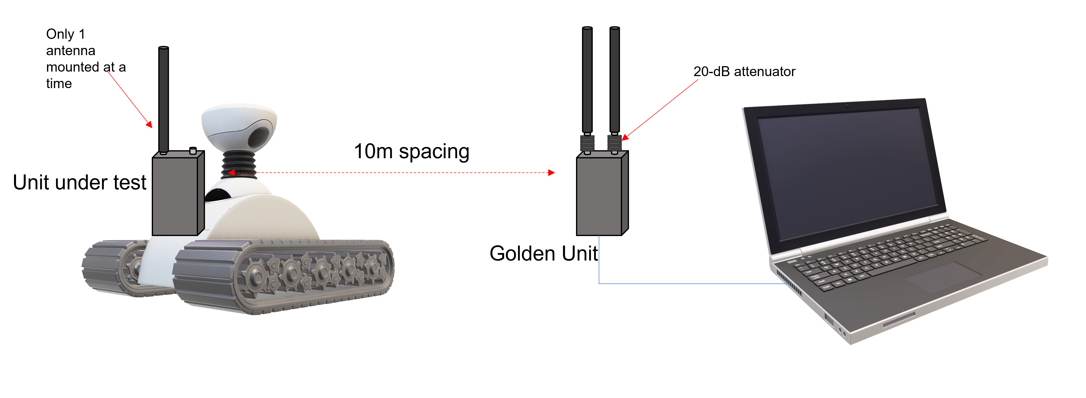
Fig. 1 Production test setup
- A golden unit is connected to a laptop.
- The golden unit is spaced at a fixed distance from the DUT (device under test). In this case, 10m.
- Attenuators are added to the golden unit to ensure sufficient path loss between the radios.
- Only one antenna is mounted to the DUT at a time.
- The path between the antennas is unobstructed, and the DUT and golden unit antennas are mounted in the same orientation so that their polarizations are matched.
- Ensure that there are no large metal reflectors around that could interfere with the link.
- Ensure that your testing environment does not introduce noise in the system that would corrupt the result.
Performance Expectations
In order to decide on a suitable go/no-go threshold for the performance, we recommend performing your tests with known good units, and then allowing for a few dB of performance spread.
Path Loss Estimate
The antennas are setup to achieve nearly ideal link conditions. Therefore, you can estimate the received signal strength using the Friis Free-Space Pathloss forumula.
Pr = Pt + Ggolden + Gdut - 32.44 - 20*log(distance) - 20*log(frequency) - atten
- Pr = Receiver power (dBm)
- Pt = Transmitted power (dBm)
- Ggolden = Antenna gain on the golden unit (dBi)
- Gdut = Antenna gain on the DUT (dBi)
- distance = distance between the DUT and golden unit (m)
- frequency = operating frequency in GHz
- atten = attenuator value (dB)
For example, if the operating frequency is 2.4-GHz, and 0 dBi antennas are used, and the transit power is 27 dBm, then the received power in this case is -53 dBm. We suggest adding sufficient pathloss so that the radio is around 5 - 10 dB higher than the failure point. For example, if you typically see the network getting overloaded at -80 dBm, you could make sure the received power is around -75 dBm.
Notes on transmitted power
The output power of the transmitter is not constant. It is controlled by four factors:
- The user setting. This is the number that you control in the
network configuration -> wirelessmenu. - The MCS rate. The radio reduces it's output power for higher MCS rates. This information can be found in each device's datasheet under the section "Additional RF Specifications"
- TPC (Transmit Power Control). When the radios are close to one another, they will attempt to reduce their output power so that the received power stays below -30 dBm.
- The regulatory limit. A power limit is applied based on the regulatory domain.
Each of these settings applies a limit to the final output power. It is possible to fix the modulation rate to MCS0 (highest power) using the commands
PHY=$(/usr/share/simpleconfig/get_fes_phy.sh)
iw wlan${PHY} set bitrates ht-mcs-2.4 0
This will not survive a reboot, and can be reset using iw wlan${PHY} set bitrates.
Test Procedure
The RF side of the radios includes both a transmitter and a receiver. You can test the receiver by looking at the RSSI reported by the DUT, and you can test the transmitter by looking at the RSSI reported by the golden unit. The RSSI can be checked by running
iw wlan${PHY} station dump | grep "signal: "
The output looks like this
signal: -51 [-58, -52] dBm
The first number is the combined signal strength, the second is the signal strength on antenna 0, and the last is the signal strength on antenna 1. In order to be able to differentiate the transmitted power on each antenna, it is necessary to only mount one antenna at a time on the DUT. You can also get the combined signal strength in json format using
ubus call iwinfo assoclist '{"device":"wlan'${PHY}'"}'
Additional Tests
The purpose of the test above was for a quick go/no-go check to make sure that there was nothing wrong with the RF side of the radio. Ideally, you would test every interface that you are using to make sure there were no issues during shipping/integration. Below are some suggested tests that you can consider adding to your production setup.
- Test the power consumption of the radios. This could be done both while the radio is idle, and while it is transmitting (at a fixed MCS rate).
- Test the Ethernet interfaces. You could run either a fast ping over the interfaces, or iperf3.
- Test the UART port. You could do a loopback test between the TX and the RX pins on the UART interface. Otherwise you could analyze your application's data coming over the interface.