Large Network Optimization
Introduction
In this document, we will discuss how to optimize the Mesh Rider radio settings for large local-area networks (LAN). The goal is to reduce the amount of background traffic to a bare minimum to keep the network running and thereby maximize the network capacity for the application payload.
Network Modes
Mesh Rider radios support three basic network topologies.
-
Mesh
- This is the default network mode that the radios are shipped in. See Figure 1.
- Every node is associated with every other node, and traffic can go from every node to every other node either directly of across multiple hops.
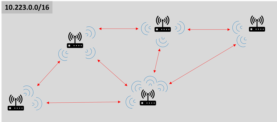
Fig. 1 Mesh Network
-
WDS AP/Client
- This is a star network as shown in Figure 2.
- All traffic goes through the AP, and clients only associate with the AP.
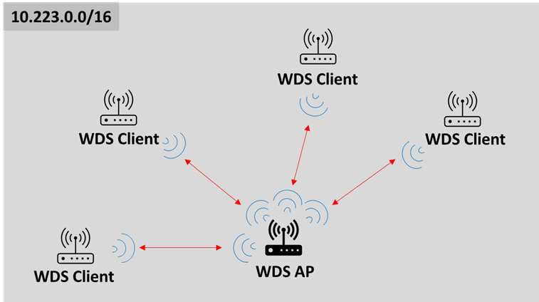
Fig. 2 Star Network
-
Dynamic Mesh
- This is a licensed feature which can support significantly larger mesh networks with zero handover latency.
- Talk to your sales representative for more information.
This document discusses optimizations for Mesh and WDS AP/Client (Star) networks. Note that star networks inherently support more nodes than mesh networks because of the smaller amount of background traffic and reduced number of peer-to-peer associations.
System Configuration and Optimization
Network Capacity in a Nutshell
Wireless transceivers are broadcast by nature. Any receiver inside of a transmitter's antenna beam will receive the transmitter's message either as recognizable data, or noise (if it cannot understand the message). In general, radio's inside of each other's coverage area need to share the total network capacity. The network capacity is measured in bits-per-second, and is influenced by
- background noise including interference
- received power
- signal distortion
Background noise affects a receiver's ability to decode the desired message. This is analogous to listening to someone talking while there is noise in the background. In Fig. 3, Radio3 cannot talk to Radio4 while Radio1 is talking to Radio2. Mesh Rider radios use a listen-before-talk (LBT) algorithm to avoid self-interference within the network, and in doing so, the radios share the total network capacity efficiently.
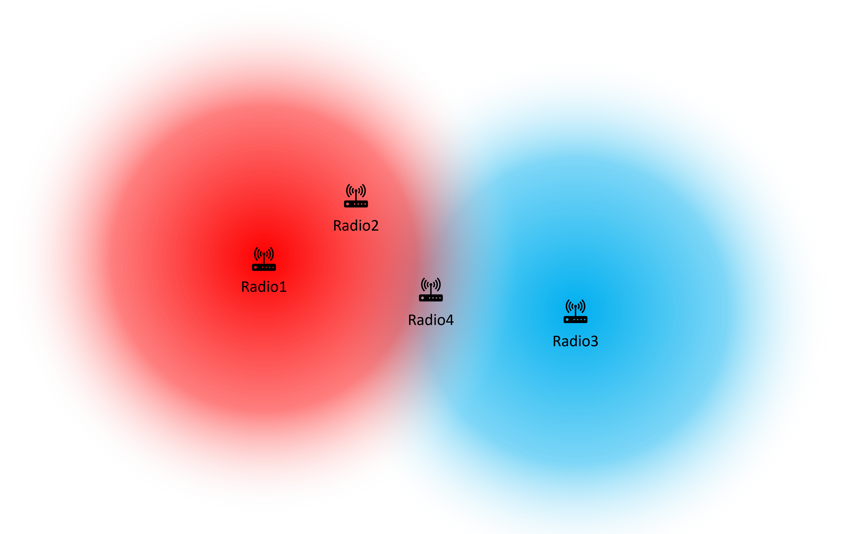
Fig. 3 Noise illustration
The recevied power is determined by factors such as the transmitted power, the antenna gain, the distance over which the signal travels, signal blockage, and contructive or destructive interference. Sometimes the overall received signal strength is good, but propagation characteristics such as small-scale fading, doppler shift, or intersymbol interference may distort the signal, reducing it's effective signal-to-noise ratio (SNR).
RF signal propagation is a complex topic, and we won't go into detail, but suffice it to say that any area of deployment supports a certain network capacity that varies over time. Networking radios usually exchange background messages which are used to maintain and optimize the network. The following sections describe how we can minimize this background traffic.
Broadcasting Behavior and Recommendations
The Mesh Rider radio handles broadcast packets in different ways for Star (AP/Client) and Mesh networks.
- For Star networks (AP/Client), a client that wants to broadcast a packet will first unicast the packet to the AP. The AP will then broadcast the packet at the lowest basic rate (6-Mbps by default) to all clients. Broadcast packets are sent only once, and there is no guarantee that they will reach their destination.
- For Mesh networks, each node that wants to broadcast a packet will broadcast it three times (for redundancy). As Mesh networks can be extended over multiple hops, any radio that receives a Mesh broadcast will re-broadcast the same packet three times unless it has already broadcast that packet.
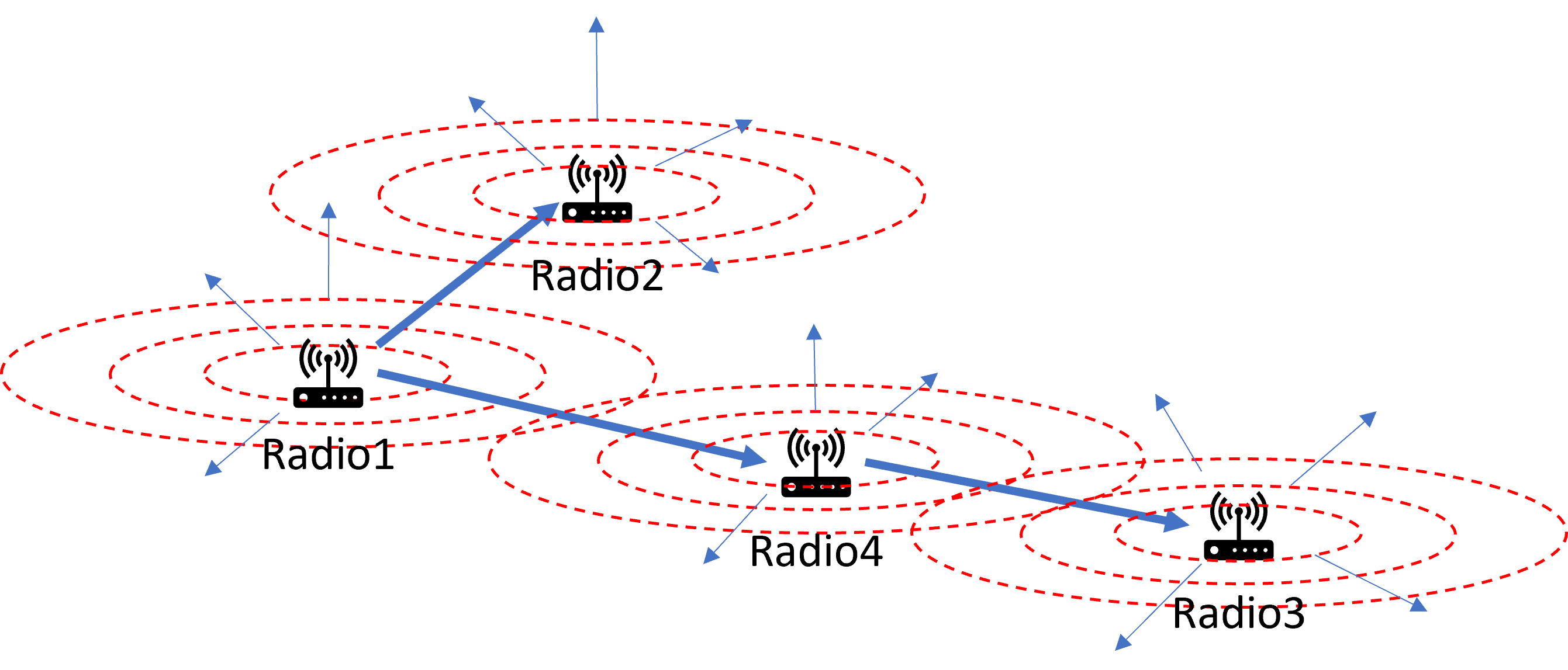
Fig. 4 Mesh broadcasting illustration
Mesh Rider radios can be configured to reduce the amount of broadcasting in Mesh mode. However, if broadcasting is used in your appication, you should make sure you understand the way protocol works before making any configuration changes.
Optimizations
The optimizations below are made based on the October 2022 Service release.
Disable the Mesh Map
The Mesh Map is a visualization tool in the GUI which aids users in understanding how traffic is routed in a mesh network. Each node needs to broadcast Mesh information in order for it to work, but it doesn't have any effect on the actual Mesh routing. Therefore it can be safely disabled.
uci set meshmap.main.enabled='0'
uci set alfred.alfred.disabled='1'
uci commit
/etc/init.d/meshmap restart
/etc/init.d/alfred restart
Disable Multicast Optimizations
If your application does not use multicasting, then we recommend disabling multicast optimizations. The default behavior of the Mesh Rider radio is to discover multicast clients, and convert multicast traffic into unicast traffic while it traverses the Mesh. Although small, it does rely on message exchange to work. If your application does use multicasting, then it is usually better to leave the optimizations enabled.
uci set network.wan.multicast_querier='0'
uci set network.bat0.multicast_mode='0'
uci commit
/etc/init.d/network restart
Disable DHCP (optional)
If your application does not use DHCP, then disable DHCP client probes.
uci set network.wan.proto='none'
uci commit
/etc/init.d/network restart
Increase OGM interval (Mesh mode only)
Increase the Mesh beaconing interval as much as your application allows (don't go higher than 10000ms). Every node broadcasts a beacon at a regular interval, and that broadcast is re-broadcast by every other node in the mesh. Therefore, mesh beacons grow with the square of the number of mesh nodes.
uci set network.bat0.orig_interval=5000
uci commit
/etc/init.d/network restart
Disable TPC
Transmit Power Control works on a peer-to-peer basis, and therefore it should be disabled. This will mean that the nodes need to be separated by a few meters to minimize packet loss. This can also be reset with /etc/init.d/network restart.
uci set wireless.radio$(/usr/share/simpleconfig/get_fes_phy.sh).dynamic_txpower=0
uci commit
wifi
Disable pinging on ath9k_watchdog
The ath9k_watchdog is a utility which constantly monitors the link between radios in the network, and takes action if any abnormalities are detected. A legacy feature of the watchdog is that it regularly pings nearby neighbors. This behavior is generally unnecessary in the latest driver, and it can be safely disabled.
uci -c "/usr/share/.doodlelabs/config/" set ath9k_watchdog.unicast_ping.disabled='1'
uci -c "/usr/share/.doodlelabs/config/" set ath9k_watchdog.broadcast_ping.disabled='1'
uci commit
/etc/init.d/ath9k_watchdog restart
In our next planned firmware release, these changes will be applied by default, and the -c "/usr/share/.doodlelabs/config/" switch will be removed.
Change the default channel bandwidth to 20-MHz
Having a wider channel bandwidth makes packet duration shorter and frees up airtime for the user's payload. In the 2.4-GHz band, it may be better to use 15-MHz to avoid Wi-Fi compatibility. This can also be reset with /etc/init.d/network restart.
uci set wireless.radio$(/usr/share/simpleconfig/get_fes_phy.sh).chanbw=20
uci commit
wifi
Adjust broadcasting behavior (Mesh mode only)
Reduce the Mesh broadcasting and re-broadcasting to the minimum. Note that bcasts_other controls the number of times a broadcast received from another radio is re-broadcast while bcasts_own controls the number of times a broadcast originating internally is transmitted. As Mesh nodes cannot always see one another, bcasts_other should be kept to a minimum of 1 if you need broadcasts to traverse the entire mesh.
uci set network.mesh_dev.num_bcasts_own=1
uci set network.mesh_dev.num_bcasts_other=0
uci commit
/etc/init.d/network restart
Mesh Limit and Discussion
Using the settings above, the radios can support around 30 nodes in a single localized mesh network where all nodes are within each other's coverage area. The mesh will support around 10 to 20 Mbps of payload, but results will vary depending on network conditions. If the mesh is spread out such that not all nodes can see each other, then a few things happen.
- You can visualize the network as if it is segregated into clusters where different clusters are optionally bridged by one or more radios.
- When this happens, it is possible for more than one radio to transmit at the same time as long as they are not in the same cluster.
- However, communications between clusters require the data packets to hop across the bridging node which multiplies the amount of data being transmitted. In Fig. 5, Radio1 and Radio2 can transmit at the same time as long as they are communicating with radios within their colored zones, but if they need to communicate with a radio in the opposite colored zone, then they will need to communicate through Radio3.
- Overall, whether the total network capacity is more or less than in the single localized mesh depends on the distribution of the mesh and the where the data needs to flow.
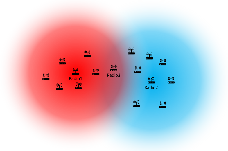
Fig. 5 Illustration of a distributed mesh
If you need more than 30 nodes in your network, you can consider
- Dynamic Mesh (talk to a sales representative)
- Segregating your network into smaller Star networks
Results
To test the above configuration changes, we created a mesh network of 16 Mesh Rider radios in the 2.4-GHz band. The point of the experiment was to test the impact of protocol overhead, and the signal strength between each set of radios was between -35 and -70 dBm to ensure good signal quality. We used a mixture of Wearable, Embedded, and Mini-OEM Smart Radios in the network.
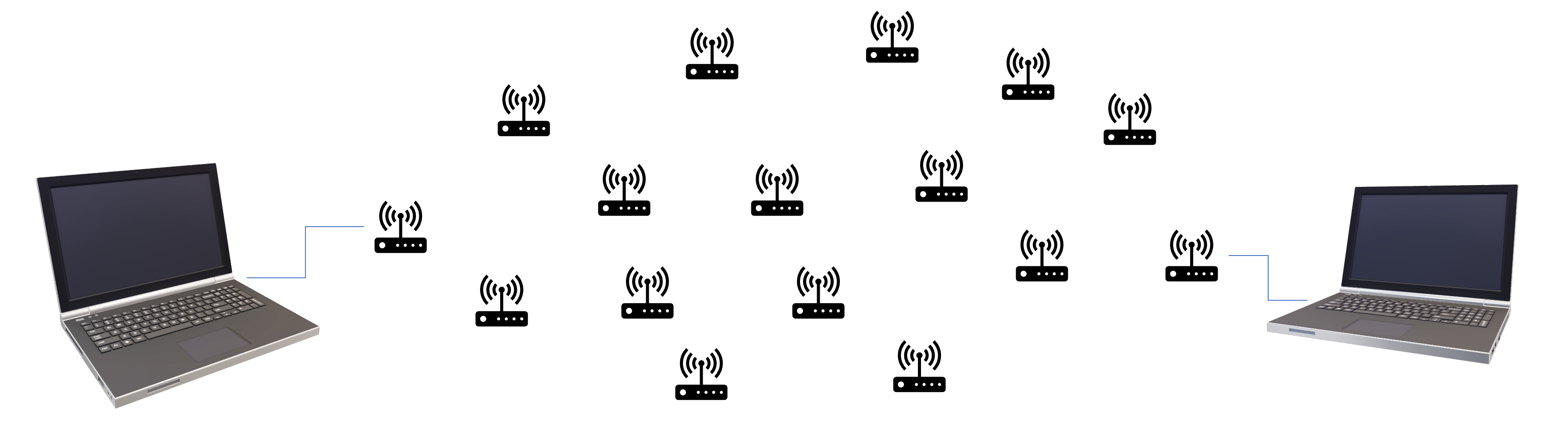
Fig. 6 Illustration of the test setup
The overall network usage can be seen by using the sysutils activity command. This shows us that background traffic occupied approximately 19% of the available air time.
root@smartradio:/tmp# sysutils activity

Checking channel activity. Please wait 5 seconds...

channel activity = 18.8286 %
TX bitrate = 58.2784 kbps
RX bitrate = 69.6864 kbps
The state of the mesh can also be found using the batctl o command. The listing below filters out indirect paths. The third column shows the time since any packet was received, and it is below 5 seconds (the mesh beaconing interval) for all nodes. The fourth column shows the transmit quality to the station in the second column out of 255. The transmit quality is acceptable for every link.
root@smartradio-301a4ebb02:/tmp# batctl o | grep "*"
* 00:30:1a:4e:bb:01    2.800s   (143) 00:30:1a:4e:bb:01 [     wlan0]
* 00:30:1a:4f:52:32    1.010s   (141) 00:30:1a:4f:51:c2 [     wlan0]
* 00:30:1a:4f:96:0e    3.450s   (151) 00:30:1a:4f:96:0e [     wlan0]
* 00:30:1a:4e:bb:22    4.140s   (151) 00:30:1a:4e:bb:22 [     wlan0]
* 00:30:1a:4e:bb:24    2.900s   (154) 00:30:1a:4e:bb:24 [     wlan0]
* 00:30:1a:4e:bb:29    1.040s   (138) 00:30:1a:4e:bb:29 [     wlan0]
* 00:30:1a:4e:bb:0a    2.660s   (192) 00:30:1a:4e:bb:0a [     wlan0]
* 00:30:1a:4f:9b:c7    1.130s   (133) 00:30:1a:4f:9b:c7 [     wlan0]
* 00:30:1a:4e:bb:06    3.980s   (116) 00:30:1a:4e:bb:26 [     wlan0]
* 00:30:1a:4f:51:c2    0.110s   (198) 00:30:1a:4f:51:c2 [     wlan0]
* 00:30:1a:4e:bb:25    3.250s   (189) 00:30:1a:4e:bb:25 [     wlan0]
* 00:30:1a:4e:bb:26    3.400s   (198) 00:30:1a:4e:bb:26 [     wlan0]
* 00:30:1a:4f:96:52    2.390s   (142) 00:30:1a:4f:96:52 [     wlan0]
* 00:30:1a:4e:bb:23    0.120s   (137) 00:30:1a:4e:bb:25 [     wlan0]
* 00:30:1a:4e:bb:09    2.980s   (167) 00:30:1a:4e:bb:09 [     wlan0]
Finally, we connected PCs to two of the radios' eth0 interfaces and ran ping and iperf tests. The round-trip-time over the network was around 3ms, and the network supported an additional 32 Mbps of application payload. It is important to note that in a real application, the network capacity depends on the number of data streams, and the size of the data packets among other things.
PS C:\> ping 10.223.0.10

Pinging 10.223.0.10 with 32 bytes of data:
Reply from 10.223.0.10: bytes=32 time=3ms TTL=64
Reply from 10.223.0.10: bytes=32 time=3ms TTL=64
Reply from 10.223.0.10: bytes=32 time=4ms TTL=64
Reply from 10.223.0.10: bytes=32 time=3ms TTL=64
PS C:\> iperf3 -c 10.223.0.10 -t 10 -i 1 -R
- - - - - - - - - - - - - - - - - - - - - - - - -
[ ID] Interval           Transfer     Bandwidth
iperf3: interrupt - the client has terminated
PS C:\Users\Aaron> iperf3 -c 10.223.0.10 -t 10 -i 1 -R
Connecting to host 10.223.0.10, port 5201
Reverse mode, remote host 10.223.0.10 is sending
[  4] local 10.223.0.90 port 53906 connected to 10.223.0.10 port 5201
[ ID] Interval           Transfer     Bandwidth
[  4]   0.00-1.01   sec  3.48 MBytes  29.0 Mbits/sec
[  4]   1.01-2.00   sec  4.72 MBytes  39.8 Mbits/sec
[  4]   2.00-3.00   sec  3.74 MBytes  31.4 Mbits/sec
[  4]   3.00-4.00   sec  3.59 MBytes  30.1 Mbits/sec
[  4]   4.00-5.01   sec  4.10 MBytes  34.0 Mbits/sec
[  4]   5.01-6.00   sec  4.00 MBytes  33.9 Mbits/sec
[  4]   6.00-7.00   sec  4.67 MBytes  39.2 Mbits/sec
[  4]   7.00-8.00   sec  4.10 MBytes  34.3 Mbits/sec
[  4]   8.00-9.00   sec  3.87 MBytes  32.5 Mbits/sec
[  4]   9.00-10.00  sec  4.06 MBytes  34.0 Mbits/sec
- - - - - - - - - - - - - - - - - - - - - - - - -
[ ID] Interval           Transfer     Bandwidth       Retr
[  4]   0.00-10.00  sec  40.4 MBytes  33.9 Mbits/sec    6             sender
[  4]   0.00-10.00  sec  40.4 MBytes  33.9 Mbits/sec                  receiver

iperf Done.
PS C:\> iperf3 -c 10.223.0.10 -t 10 -i 1
Connecting to host 10.223.0.10, port 5201
[  4] local 10.223.0.90 port 53908 connected to 10.223.0.10 port 5201
[ ID] Interval           Transfer     Bandwidth
[  4]   0.00-1.01   sec  4.50 MBytes  37.4 Mbits/sec
[  4]   1.01-2.01   sec  4.00 MBytes  33.5 Mbits/sec
[  4]   2.01-3.01   sec  3.00 MBytes  25.1 Mbits/sec
[  4]   3.01-4.01   sec  4.00 MBytes  33.7 Mbits/sec
[  4]   4.01-5.01   sec  3.50 MBytes  29.4 Mbits/sec
[  4]   5.01-6.01   sec  4.00 MBytes  33.5 Mbits/sec
[  4]   6.01-7.01   sec  3.75 MBytes  31.4 Mbits/sec
[  4]   7.01-8.01   sec  3.38 MBytes  28.3 Mbits/sec
[  4]   8.01-9.00   sec  4.38 MBytes  37.1 Mbits/sec
[  4]   9.00-10.00  sec  3.88 MBytes  32.5 Mbits/sec
- - - - - - - - - - - - - - - - - - - - - - - - -
[ ID] Interval           Transfer     Bandwidth
[  4]   0.00-10.00  sec  38.4 MBytes  32.2 Mbits/sec                  sender
[  4]   0.00-10.00  sec  38.2 MBytes  32.0 Mbits/sec                  receiver

iperf Done.
Quick Summary Of Network Optimization
Important: In mesh mode, it is necessary to stagger the power on of each device with around 10 seconds of delay to prevent all of the authentication/association packets flooding the network.
We will use the command line to configure the radios as it is significantly faster when you are configuring a large number of nodes. To apply the same configuration to a large number of nodes, we strongly recommend either creating your own firmware image, or using a factory reset script for each radio. Details can be found in our Production Firmware Customization Guide (link to be added).
The optional steps listed below have less impact on background traffic, but you should apply them if you don't need the features.
# Disable the Mesh Map (mesh mode only)
uci set meshmap.main.enabled='0'
uci set alfred.alfred.disabled='1'

# Disable multicast optimizations (optional)
uci set network.wan.multicast_querier='0'
uci set network.bat0.multicast_mode='0'

# Disable sending DHCP probes (optional)
uci set network.wan.proto='none'

# Increase the mesh beaconing interval to 5 seconds (mesh mode only)
uci set network.bat0.orig_interval=5000

# Disable Transmit Power Control
uci set wireless.radio$(/usr/share/simpleconfig/get_fes_phy.sh).dynamic_txpower=0

# Increase the channel bandwidth to 20-MHz (use 15-MHz for 2.4-GHz radios)
uci set wireless.radio$(/usr/share/simpleconfig/get_fes_phy.sh).chanbw=20

# Reduce broadcast redundancy to 1 (no redundancy), and do not re-broadcast received broadcast packets (breaks mesh hopping for broadcast packets)
uci set network.mesh_dev.num_bcasts_own=1
uci set network.mesh_dev.num_bcasts_other=0

# disable ath9k_watchdog pings
uci -c "/usr/share/.doodlelabs/config/" set ath9k_watchdog.unicast_ping.disabled='1'
uci -c "/usr/share/.doodlelabs/config/" set ath9k_watchdog.broadcast_ping.disabled='1'

# Commit changes and restart relevant services
uci commit
/etc/init.d/ath9k_watchdog restart
/etc/init.d/meshmap restart
/etc/init.d/alfred restart
/etc/init.d/network restart