nano-OEM and Helix Mesh Rider Radio – Eval Kit Connector Descriptions
Connectors
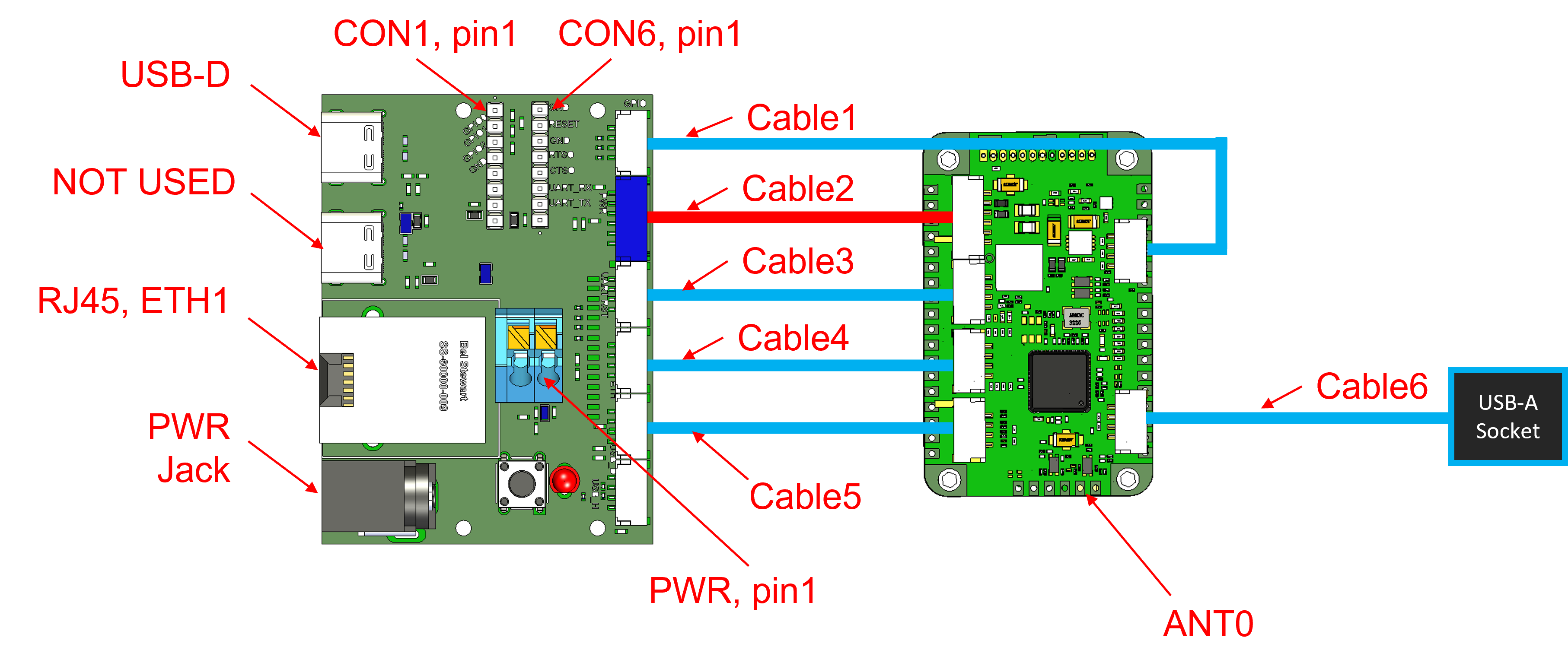
Cables
| Cable Number | Description |
|---|---|
| Cable1 | 20cm, 4-position JST-GH to JST-GH cable |
| Cable3, Cable4 Cable5 | 10cm, 4-position JST-GH to JST-GH cable |
| Cable2 | 20cm, 6-position JST-GH to JST-GH cable |
| Cable6 | 10cm, 4-position JST-GH to USB-A Socket. USB-Host connector |
Pin Headers
CON1
- 2-mm pin header
| Pin Number | Direction | Voltage | Pin Description |
|---|---|---|---|
| PIN 1 | I/O | 0V to +2.8V | GPIO0 |
| PIN 2 | I/O | 0V to +2.8V | GPIO1 |
| PIN 3 | I/O | 0V to +2.8V | GPIO2 |
| PIN 4 | GND | GND | |
| PIN 5 | NOT USED | ||
| PIN 6 | NOT USED | ||
| PIN 7 | NOT USED | ||
| PIN 8 | NOT USED |
CON6
- 2-mm pin header
| Pin Number | Direction | Voltage | Pin Description |
|---|---|---|---|
| PIN 1 | GND | GND | |
| PIN 2 | I | 0V to +2.8V | Reset pin (pulled HIGH internally). Pull LOW to reset |
| PIN 3 | GND | GND | |
| PIN 4 | NOT USED | ||
| PIN 5 | NOT USED | ||
| PIN 6 | I | 0V to +3.3V | UART_RX |
| PIN 7 | O | 0V to +3.3V | UART_TX |
| PIN 8 | GND | GND |
Snap-in Connector (PWR)
| Pin Number | Direction | Voltage | Pin Description |
|---|---|---|---|
| PIN 1 | GND | GND | |
| PIN 2 | I | +5-V | PWR |
Standard Connectors
- USB-D: USB-C Device Connector supporting Ethernet over USB only
- RJ45: RJ45 Jack connected to Eth1
- PWR Jack: RAPC712X Barrel connector. 2.5-mm inner diameter, 6.3mm outer diameter.
- ANT0: MMCX Female Connectors