Multiband-OEM User Guide (OEM Form Factor)
Overview
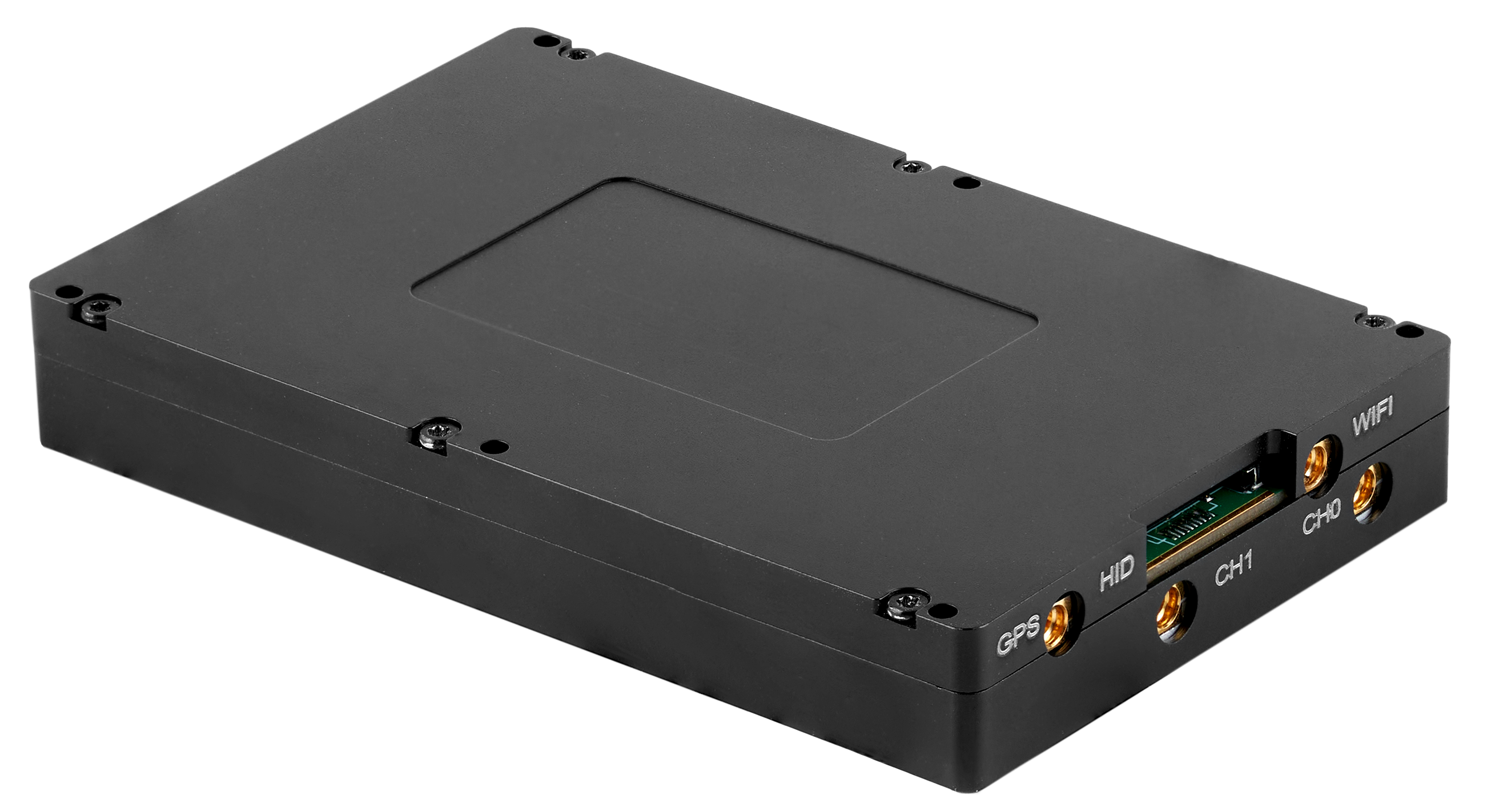
The Multiband-OEM Mesh Rider radio is a small, rugged, light-weight IP-based OEM radio designed for military, law-enforcement, and emergency services personnel. With cutting-edge technology and rugged durability, this radio is designed to deliver reliable, secure, and uninterrupted communication in the most challenging environments.
The Multiband-OEM radio employs Doodle Labs' patented Mesh Rider® technology with state-of-the-art RF and networking capabilities that enable communication further, faster, and more reliably than any comparable solution on the market. Devices can connect to the Multiband-OEM radio over the USB, Ethernet or Wi-Fi interfaces.
This user guide details the main features of the radio, and walks you through the setup and usage of the radio.
Hardware Introduction
Interfaces
Fig. 1 lists the Multiband OEM's external interfaces.
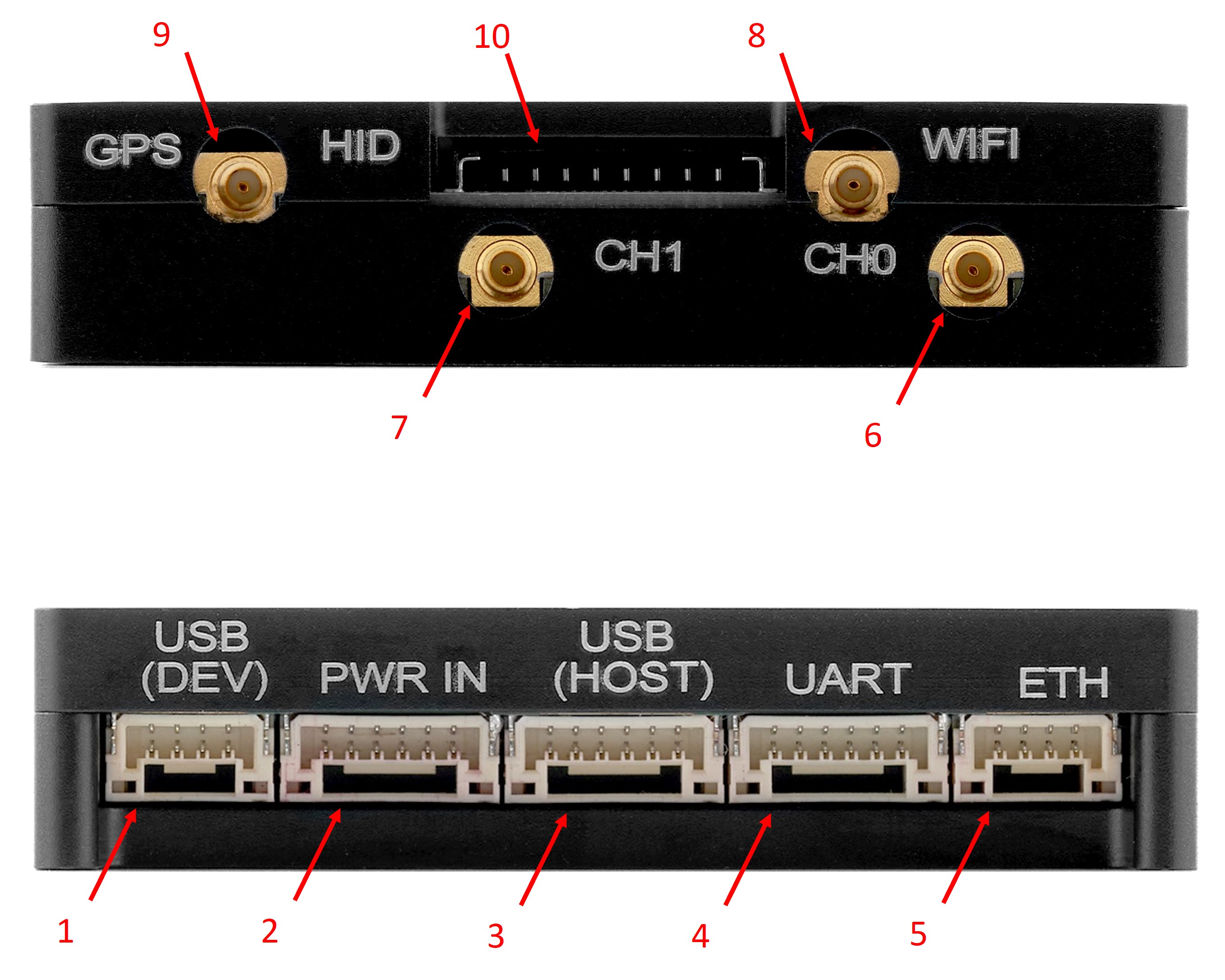
Fig. 1 Hardware Interfaces
- USB device data and power port
- Power port
- USB host port
- UART port
- Ethernet port (ETH1)
- Mesh Rider Antenna 0 (MMCX-Female)
- Mesh Rider Antenna 1 (MMCX-Female)
- Wi-Fi Antenna (MMCX-Female)
- GPS Antenna (MMCX-Female)
- Auxiliary port (HID Board)
The full pinout for each interface is available on your product's landing page.
HID Board attachment
Fig. 2 shows how the HID auxiliary board is attached to the Multiband OEM radio. Pin 1 on the board-to-board cable is marked.
Warning
Forcing the cable into the receptacle at an angle can damage the connector.
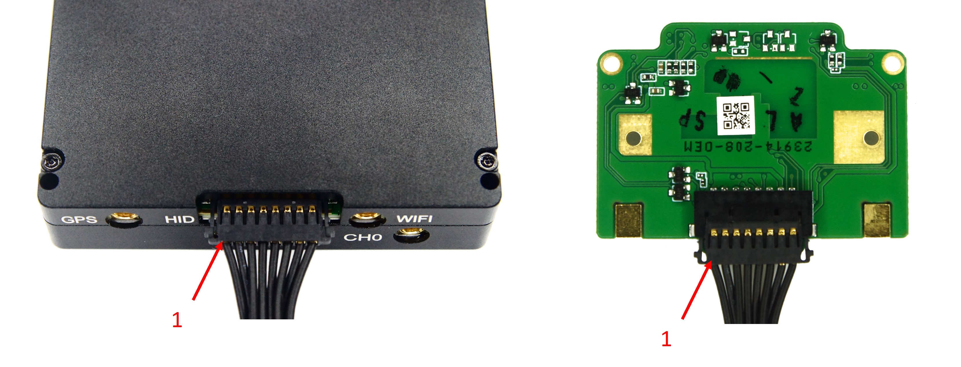
Fig. 2 Connecting the HID Expansion Board to the OEM Radio
Buttons and indicators
Fig. 3 shows the HID expansion board and it's interfaces.
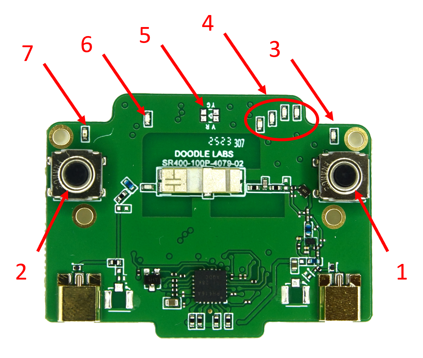
Fig. 3 HID Expansion Board
- Power button
- Turbo button
- Power LED
- Mesh Rider indicator (LED group)
- Input voltage indicator
- Wi-Fi indicator
- Turbo LED
The expansion board is designed to emulate the Multiband Wearable's buttons and interfaces. Table 1 list summarizes the Buttons and indicators, and their functions.
Table 1 Buttons and Indicators summary
| Button/Indicator | Function |
|---|---|
| Power Button (ON) | Switch the radio between different power states (see table 2) |
| Turbo Button | Manually toggle between 1x1 and 2x2 MIMO operation for power savings |
| Power LED | Indicate the power mode |
| Turbo LED | Indicate whether the radio is in 1x1 or 2x2 MIMO mode |
| Mesh Rider Indicator | Indicate the RSSI on the Mesh Rider interface |
| Input voltage indicator | Indicate the battery status |
| Wi-Fi indicator | Indicate the Wi-Fi signal strength |
| Battery Power Button | switch ON/OFF the battery. Press and hold for 5 seconds |
The radio's power states are described in table 2.
Table 2 Power States
| Mode | Description | Power LED Status |
|---|---|---|
| On | The radio is fully on | On |
| Off | The radio is in extreme low-power mode. Only essential components remain on | Off |
The radio's power button functionality is described in table 3.
Table 3 Power Button Usage
| Power Button Action | Operation |
|---|---|
| 4-second press | On -> Off Off -> On |
Table 4 shows LED behavior for different operating states of the radio.
Table 4 LED Behavior for different Operating States
| Condition | Power LED | Wi-Fi Indicator | Mesh Rider Indicator |
|---|---|---|---|
| Radio booting up | slow blinking (1200ms period) | slow blinking (1200ms period) | slow blinking (1200ms period) |
| ON | Steady | See table 5 | See table 5 |
| Both Power button and Turbo button held and preparing to factory reset on release | fast blinking (600ms period) | fast blinking (600ms period) | fast blinking (600ms period) |
Table 5 shows the behavior of the Mesh Rider and Wi-Fi indicators. The Mesh Rider indicator is a groupd of LEDs used to indicate signal strength and link conditions. The LEDs light up from left to right depending on the signal strength, with the leftmost LED indicating the lowest signal strength.
Table 5 Mesh Rider and Wi-Fi indicators
| Status | Mesh Rider indicator | Wi-Fi indicator |
|---|---|---|
| Not associated | OFF | OFF |
| Associated but link lost | Slow blink (1800ms period) | Steady |
| Connected | Steady, number of LEDs illuminated dependent on RSSI | Steady |
Table 6 shows the Turbo button and LED behavior.
Table 6 Turbo button and LED behavior
| Turbo button action | Mode | LED behavior |
|---|---|---|
| 2-second or longer press | 1x1 SISO -> 2x2 MIMO | Blinking (1200ms period) until link re-established -> Steady |
| 2-second or longer press | 2x2 MIMO -> 1x1 SISO | Blinking (1200ms period) until link re-established -> Off |
Table 7 shows the input voltage level indicator behavior.
Table 7 Input voltage level indicator behavior
| Input voltage | LED behavior |
|---|---|
| > 7.84 V | Steady, Green |
| 7.39 - 7.84 V | Steady, Yellow |
| 6.5 - 7.39 V | Steady, Red |
| < 6.5 V | blinking (1200ms period), Red |
Evaluation Kit Board
An EVK board can be purchased with the Multiband OEM Mesh Rider Radio for quick evaluation. Fig. 4 shows the EVK board connected to the OEM radio. Full details of the EVK are available on your product's landing page.
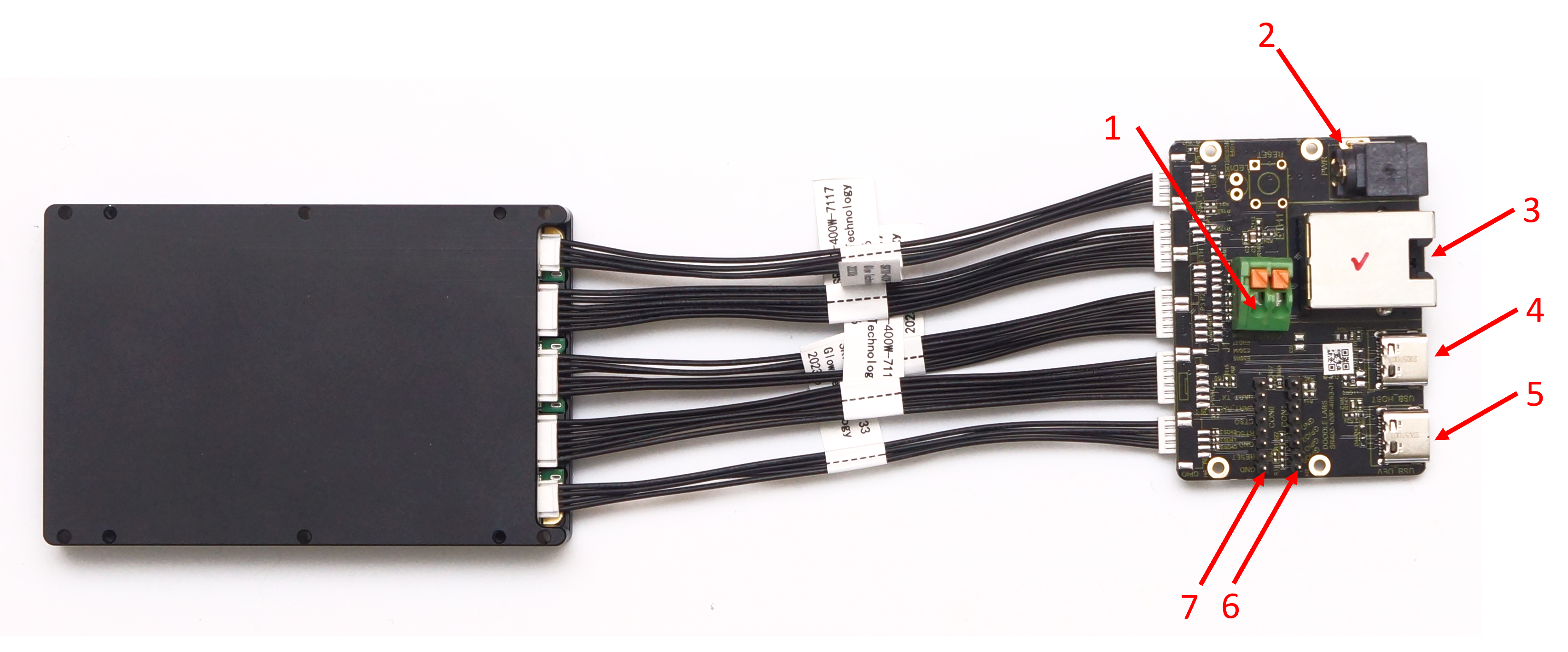
Fig. 4 EVK board connected to OEM radio
- Power Connector
- Alternative Power Connector (2.5mm inner diameter, 5.5mm outer diameter)
- Ethernet Connector (ETH1)
- USB-C Host Connector
- USB-C Device Connector
- CON1 (NOT USABLE)
- CON6 (see pin diagram on product landing page)
Important
The EVK board is a common PCB used by other Doodle Labs products, and as such, not all parts are populated or usable.
For the Multiband OEM, CON1 is NOT USABLE. On CON6, only UART pins (and GND) are usable.
Factory Reset
Factory Reset over hardware can only be achieved using the HID interface board.
To factory reset, hold down both the Turbo button and the Power button until the indicators all start flashing. After that, release the two buttons and wait for the device to reboot. A factory reset may take up to 5 minutes. Do not power down the unit during the factory reset.
Initial Setup
Hardware setup
Connect the HID interface board, and the EVK board to the Multiband OEM radio following the guidelines above, along with the antennas provided in your evaluation kit.
Info
Typically Android tablets support USB reverse tethering while Android phones only support USB tethering. Some devices support both. USB reverse tethering allows the Android device to get an internet connection from a connected device while USB tethering allows the Android device to share it's own LTE connection.
- As soon as power is applied to the radios, all of the LEDs will blink once.
- After powering the radio, hold down the Power button for 2 seconds to turn the unit on. The Power LED will blink until the unit has fully booted, at which point it will be steady.
- While booting up, both the Wi-Fi and Mesh Rider indicators will blink. They will switch to a slow blink after boot-up while waiting for a connection. If you have turned on any other radio, the Mesh Rider indicator will eventually hold steady once the radios are connected.
- If you connect to the radio over it's Wi-Fi interface, then the Wi-Fi indicator will hold steady.
Important
The radio can be switched between Normal mode and Turbo mode. In Normal mode, the radio is limited to 1x1 (SISO) operation, and the throughput is limited to 6 Mbps. This is useful for power savings when the network traffic is light. Holding down the Turbo button for 2 seconds will switch the radio to Turbo mode. In Turbo mode, the radio operates in 2x2 (MIMO) configuration, and there is no throughput limit.
It is possible to modify the Turbo mode behavior in the Services -> Wearable Configuration menu.
Connecting to the OEM
The EVK board uses standard wiring to suppport the Ethernet, USB-Host, and USB-Device interfaces. Both the USB-Host and USB-Device ports support USB 2.0.
Wi-Fi Connection
You can connect to the radio over it's built-in Wi-Fi radio. By default, the built-in Wi-Fi radio starts up an Access Point with SSID DoodleLabsWiFi-<last 6 hex digits of MAC> and password DoodleSmartRadio. Remember to connect the Wi-Fi antenna to the Multiband OEM Radio.
See the Software Setup section for details on IP addressing.
USB Connection (OEM as USB Device)
Alternatively, you can connect to the radio over the USB port on the EVK. You can connect to the radio's USB port from a PC or a smart device (e.g. tablet or phone) which supports USB reverse tethering. In this mode, the OEM is a USB Device, and the PC/tablet/phone is a USB Host.
See the Software Setup section for details on IP addressing.
Ethernet Connection
The EVK board provides a standard RJ45 Jack for Ethernet.
See the Software Setup section for details on IP addressing.
USB Connection (OEM as USB Host)
As a final alternative, you can use the Multiband OEM radio's USB-Host port to connect to a USB Device such as an Android Smart Phone with a USB OTG port. Doodle Labs does not provide a USB dongle for this purpose, however, you can use any off-the-shelf USB-C to USB-A dongle as long as it is limited to USB 2.0. USB 3.0 is not supported, and the USB 3.0 wires should not be connected to the OEM Mesh Rider radio.
Note
When an Android device is in USB Device mode, it typically goes to USB tethering mode for Ethernet over USB support. In USB tethering mode, the Android device typically attempts to share it's existing internet connection by acting as a gateway to the internet. The Android device usually takes on a static IP address and runs a DHCP server. The details depend on the device and the OS. In this mode, the Mesh Rider Radio is not reachable using it's 10.223.0.0/16 IP address.
Software setup
The Multiband OEM Mesh Rider radio uses the same IP addressing scheme as all Mesh Rider radios. Therefore, you will need to assign a static IP address to your host machine in the 10.223.0.0/16 subnet in order to access the radios. This is true for both the USB connection and the Wi-Fi connection. Details on how to configure a static IP address differ depending on your operating system, and guidelines for a Windows 10 PC are shown here.
If you are connecting to the radio over the USB port, then your system will need to have the driver for the LAN9500A chipset installed. It should be available by default in Windows machines, most Linux distributions (smsc95xx driver), and Android devices which support USB reverse tethering. Fig. 5 shows the Ethernet 2 adapter (LAN9500A USB to Ethernet) appearing after plugging in the OEM Mesh Rider radio in a Windows 10 machine.
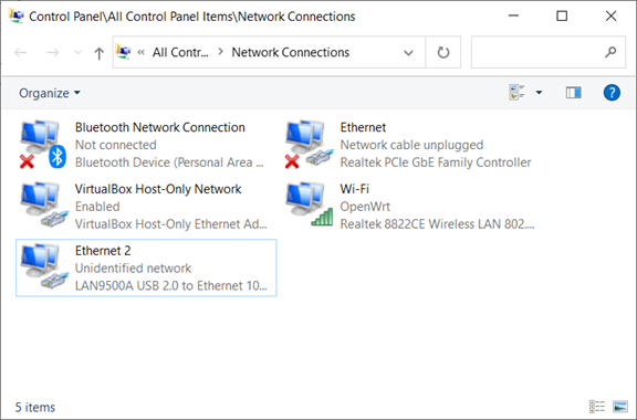
Fig. 5 LAN9500A USB to Ethernet adapter in Windows 10
The default configuration of the Mesh Rider radios allows them to automatically form a mesh on first boot-up without any configuration changes. You can immediately run IP-based connections over the Mesh Rider network. That said, you should at least modify the following settings for security:
- Add a root password
- Modify the Mesh Rider radio's SSID and Password
- Modify the Wi-Fi radio's SSID and Password
You will be prompted to modify the root password the first time you attempt to login to the radio over the web GUI. Open a web browser and navigate to the IP address printed on the label of the device. After changing the root password, you can navigate to the Simple Configuration page.
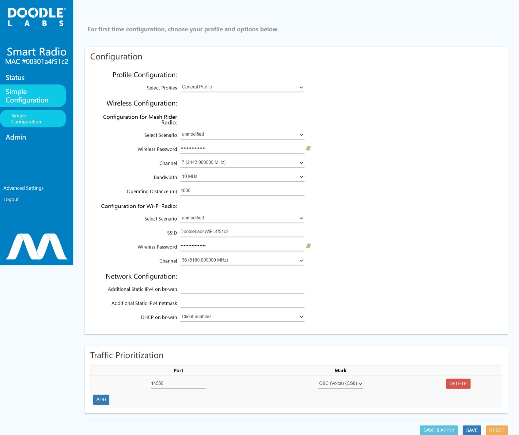
Fig. 6 Simple Configuration page
This page allows you to modify the most common settings on the radio in one step. Aside from the changes mentioned above, you can optionally
- Disable the DHCP client if it isn't required. This will leave only the default 10.223.0.0/16 IP address.
- Change the default channel and bandwidth of the Mesh Rider radio.
- Change the default channel of the Wi-Fi radio.
Make sure to make similar changes on all other radios to maintain connectivity. We encourage you to read through our guides in the Technical Library for additional tips on working with Mesh Rider radios.
Networking Information
As with all Mesh Rider radios, the default configuration behaves like a wireless ditributed layer-2 switch. Connecting devices to Mesh Rider radios is similar to connecting the same devices to an Ethernet switch. The Mesh Rider network passes traffic over the mesh transparently, and devices which need to communicate with one another need to be on the same IP subnet. Details on the Mesh Rider's networking modes are available here.
General Usage
The Multiband OEM Mesh Rider radio is designed to be integrated into an end product. Examples of common applications includes long-range industrial UAVs and UGVs, factory automation, and connected teams. The OEM Mesh Rider radio could also act as a gateway to the internet. There are also other advanced features that were not discussed in this guide. For more information, please look through the Doodle Labs Technical Library.