Optimizing the RF Link
Introduction
One of the most frequent questions we get is "how far can your radios go?" This is not an easy question to answer, as there are many factors that go into this. This application note gives an overview of the major considerations and discusses methods to optimize the link performance. Our intention is to provide some useful insights which can help during the design of an RF link.
Our overall recommendations is
- Include around 10-15 dB of fade margin to account for changing environmental and operating conditions
- Use the highest gain antenna that your application allows, and if possible, separate the antennas by a half-wavelength in an orthogonal arrangement.
- The objective is to operate the link with the highest SNR possible (the sweet spot for Mesh Rider Radio is around -40 dB to -70 dB RSSI).
To get a quick assessment of the achievable throughput, use our Throughput Estimation tool.
Factors affecting the RF link
Fundamental physical laws allow us to express the RF Link Range in simple terms as
RF Link Range=f(TX Power, RX Sensitivity and Channel Bandwidth, Operating Frequency and Antenna Gain, Path Loss, Noise and Interference)
Unpacking this shows us that many factors affect the RF link range. In the following sections, we will discuss each of them in simple terms, and also suggest methods to overcome any limitations they impose. If you just want to jump quickly to software configuration sections, please use the links below.
- Configuring TX power
- Configuring short-range transmit power control
- Configuring short-range receiver gain
- Configuring channel bandwidth
- Configuring MCS rates and diversity
- Optimizing for latency or throughput
TX Power
Higher RF transmit power makes signals go farther. For license free bands, the regulatory requirement limits the amount of RF transmit power. Mesh Rider Radios feature the maximum RF power (1W or 30 dBm) that is allowed by the FCC.
You can see the effect of output power on the link by using our Throughput Estimation tool. The output power of the radio is not constant. It is controlled by four factors:
- The user setting.
- This is the number that you control in the
network configuration -> wirelessmenu.
- This is the number that you control in the
- The MCS rate.
- All Power AAmplifiers exhibit non-linear gain as they approach their output power limits.
- This non-linearity distorts the RF signal and prevents the transmitter from operating at it's power limit when transmitting at high modulation rates.
- There is usually a power backoff of 6-7 dB when transmitting at the highest modulation rate.
- The actual backoff is detailed in your product's datasheet.
- TPC (Transmit Power Control).
- When the radios are close to one another, they will attempt to reduce their output power so that the received power stays below -30 dBm.
- This can be disabled if desired.
- The regulatory limit.
- A power limit is applied based on the regulatory domain.
Each of these settings applies a limit to the final output power. Note that TPC is a peer-to-peer protocol. For large networks, it is recommended to turn it off to reduce the network overhead. This is discussed in our Large Network Optimization guide.
TX Power Configuration
You can adjust the user setting in the GUI under network configuration -> wireless after clicking edit next to the Mesh Rider radio interface. The limits of the selectable power are shown in a drop-down box. Refer to Fig. 1.
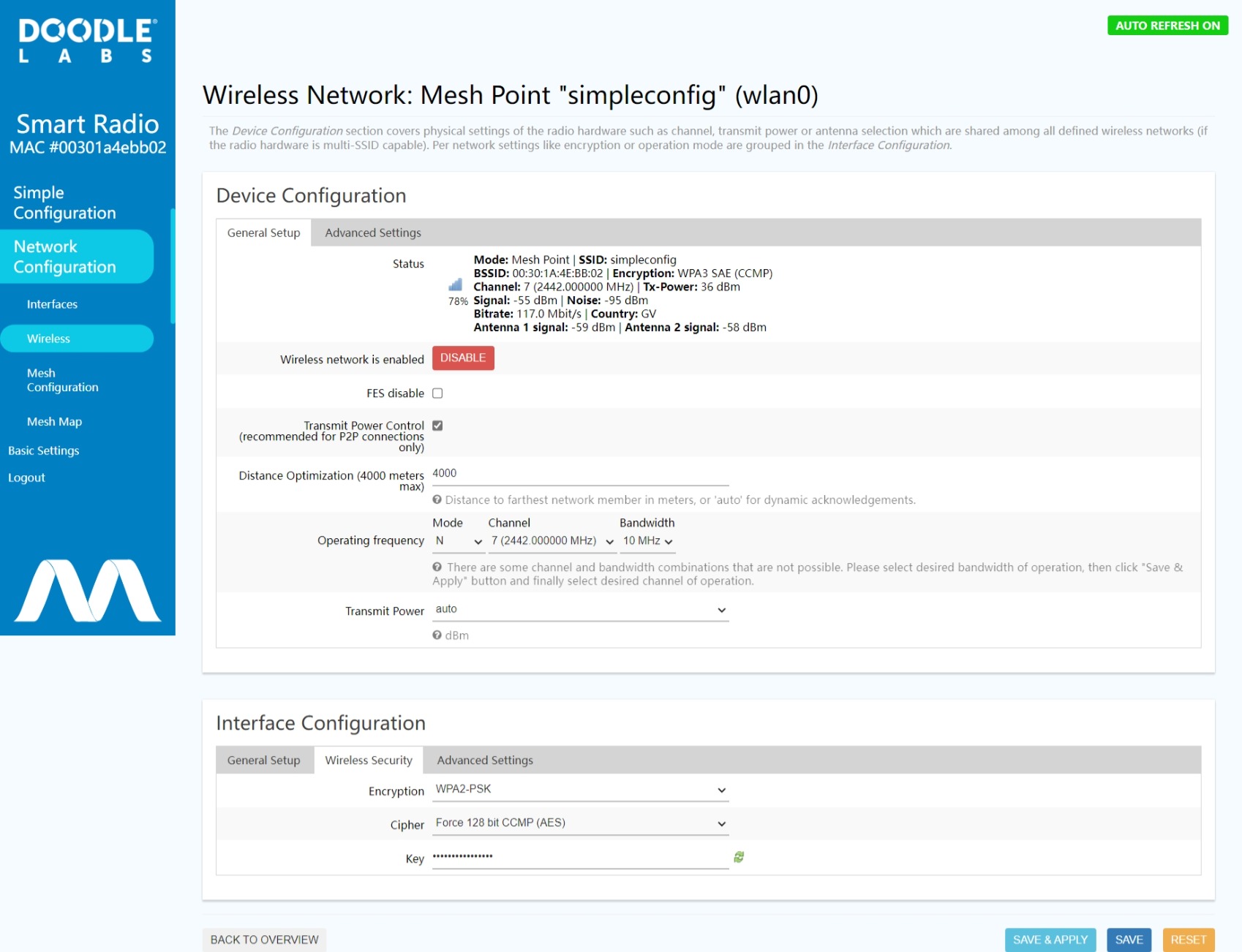
Fig. 1 Wireless Configuration Menu
You can also perform a long-term power change using the following commands
PHY=$(/usr/share/simpleconfig/get_fes_phy.sh)
uci set wireless.radio${PHY}.txpower=23
uci commit
wifi
This sets the txpower to 23 dBm. You can also perform a quick tx power setting which does not survive a reboot using the command
PHY=$(/usr/share/simpleconfig/get_fes_phy.sh)
iw wlan${PHY} set txpower fixed 2300
The setting is in millibels, hence 2300 is 23 dB. You can reset the tx power to auto using iw phy phy${PHY} set txpower auto.
Short-Range and Transmit Power Control
In some situations it is necessary to operate the Mesh Rider Radios at very short range (e.g. a drone/robot operating near the control station before moving away). The Mesh Rider Radio includes transmit power control (TPC). When a node detects another node that is too close, messages are exchanged between the nodes so that they each reduce their transmit power to an optimal level. How close units can get to each other depends on the model as path loss is frequency dependent. For reference, RM-2450-2J-X works well to within about half a meter. For unicast messages, TPC works on a peer-to-peer basis. i.e. the TX power to each peer is individually adjusted.
You can turn ON/OFF TPC in the GUI, under network configuration -> wireless after clicking edit next to the Mesh Rider radio interface. This is shown in Fig. 1. You can also use the command prompt as in the following example (this turns OFF TPC).
PHY=$(/usr/share/simpleconfig/get_fes_phy.sh)
uci set wireless.radio${PHY}.dynamic_txpower='0'
uci commit
wifi
See also Aggressive TPC.
RX Sensitivity and Channel Bandwidth
RX Sensitivity is outside of the user's control except that it is possible to modify the channel bandwdith (discussed below). The sensitivity of your radio is detailed in it's datasheet.
- Mesh Rider radios use high-gain front-end LNAs to get the best possible sensitivity.
- Our Qualcomm-based baseband radios include best-in-class processing which allow them demodulate
- low SNR signals
- signals with a high degree of irregular distortion or missing information
- rapidly changing signals
In general, reducing the channel bandwidth affords you more range, and better resilience to constant co-channel interference. This comes at the cost of reduced bandwidth, and poorer resilience to intermittent interference. Consider the highly simplified image below. Our original message is impaired by noise which has some elements of random background fluctuation plus some intermittent surges of interference.
- With a narrow bandwidth, we are attempting to talk over this noise. The power of each data symbol is integrated over a longer duration, and this smooths out the noise.
- With a wide bandwidth, we are able to talk in-between the intermittent interference, but the integration time for each data symbol is shorter, so we are more susceptible to constant background noise.
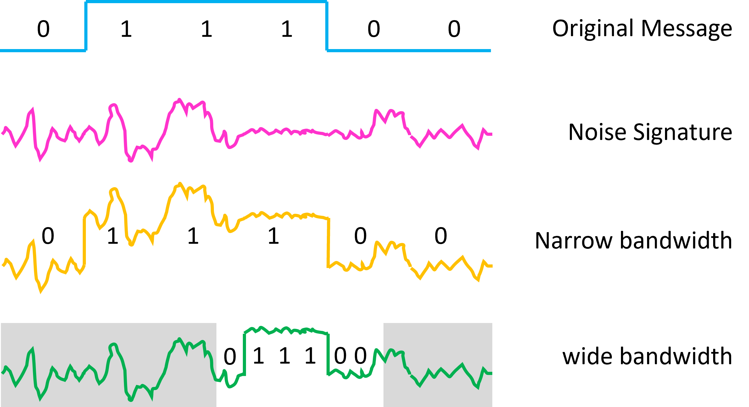
Fig. 2 Noise and Channel Bandwidth
Use our Throughput Estimation tool to see the effect of channel bandwidth on network capacity. Make sure to include sufficient margin in your network capacity, especially for realtime applications which may transmit very bursty traffic and require low latency.
Configuring Channel Bandwidth
You can adjust the channel bandwidth by navigating to network configuration -> wireless and clicking edit next to the Mesh Rider radio interface (Refer back to Fig. 1). You should do this on the remote radios followed by the locally connected radio. You can also adjust the channel bandwidth in the command prompt using the uci interface. For example,
PHY=$($(/usr/share/simpleconfig/get_fes_phy.sh))
uci set wireless.radio${PHY}.chanbw=5
uci commit
wifi
In radios with only one radio, PHY is always 0. The commands above set the channel bandwidth to 5-MHz. The available settings depends on your radio model, but usually include 3, 5, 10, 15, and 0 (for 20-MHz).
Configuring short-range receiver sensitivity
The radio also includes a switch called Aggressive TPC. This can be accessed in the web GUI under network configuration -> wireless after cliking edit next to the Mesh Rider radio interface (See Fig. 1). Aggressive TPC is under the control of the built-in transmit power control (TPC) algorithm, but it actually affects the receive-chain RF amplifiers. Enabling Aggressive TPC allows the radio to perform a quick reduction in the received power when it is too high. However, this also affects the sensitivity of the radio. Therefore, if the receive-side amplifiers are disabled, the long-range performance of the radio to a distant node will degrade. You can also disable Aggressive TPC in the command prompt using the commands
PHY=$($(/usr/share/simpleconfig/get_fes_phy.sh))
uci set wireless.radio${PHY}.dynamic_txpower_aggr='0'
uci commit
wifi
See also Short-Range and TPC.
Operating Frequency and Antenna Gain
Operating Frequency and Antenna Gain are closely linked. To first order, the propagation path loss does not depend on the operating frequency. Take a isotropic antenna in free space for example, where a wave is launched in space and the energy is contained on the surface of a sphere. As the wave moves away from the antenna, the sphere gets bigger and the energy in the wave spreads out. The law of conservation of energy tells us that the energy at any distance is the same as it was when it was launched, except that it is spread out over a larger sphere. The operating frequency is not relevant in this example.
Operating frequency comes into the picture when we consider the antenna's aperture (it's capture surface area). For two dipole antennas with the same radiation pattern, but different operating frequency, the higher-frequency antenna is smaller than the lower-frequency in proportion to their wavelengths, and the antenna aperture is smaller in proportion to the square of their wavelengths.

Fig. 3 Illustration of RF propagation
Beyond the first-order analysis, low frequency signals have lower transmission losses and are able to penetrate through vegatation. They also have higher refractivity to go around the obstacles. All these characteristics allow for longer-distance communication. However, at lower frequencies, the Fresnel zones (discussed later) are larger and create obstruction for low height operations. The antenna size and weight are also larger at low frequencies. Therefore, for the same antenna size, it is possible to select a higher-gain antenna at higher operating frequencies.
Hence, a careful balance is required to meet the system requirements. Mesh Rider Radios are available in many frequency bands in the same form factor. This allows a simple swap of the radio module and makes it easier to meet various requirements the system will need to meet.
Antenna Gain and Directivity
Antennas are passive amplifiers of RF signals. They amplify signals and increase signal reception without introducing any signal distortion. In general terms, the phrase "bigger the better" applies well to antennas. There are many variables like gain, directivity, polarization, and position that go into the proper selection of antennas.
Antennas are discussed in detail in our Antenna Recommendations for UAS and UGVs guide.
In general, we recommend using the highest gain antenna that can be accommodated by the size and directivity requirements of the system, and space antennas orthogonally and at least a ½ wavelength apart.
MIMO Technology
Mesh Rider Radios employ state-of-the-art 2×2 MIMO technology (Multi-In and Multi-Out). MIMO is a game changer in the field of wireless communication. MIMO uses multi-path reflected signals and powerful DSP algorithms to help improve speed and reliability. For best performance 2x2 MIMO requires two antennas for transmit and receive. Having two antennas allows the radio to use either spatial-multiplexing to improve the data rate or spatial-diversity to improve the reliability of the link.
In spatial-diversity, the same stream of data is sent redundantly over both antennas and combined at the receiver in an intelligent way to optimize the link quality and SNR. Depending on the application, it may be beneficial to mount one antenna horizontally and the other vertically to get the most diversity in the polarization, or to mount both antennas horizontally (for example) to get the most power if the polarization is known.
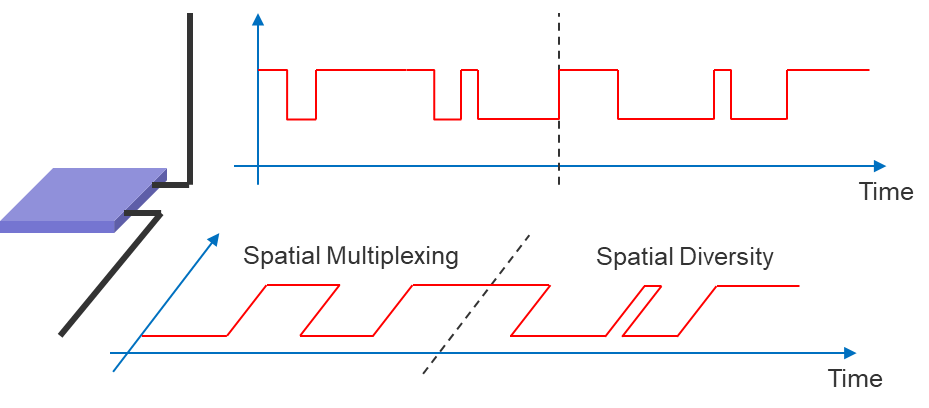
Fig. 4 - Spatial Multiplexing vs Spatial Diversity
In spatial-multiplexing, two different streams of data are sent to the two antennas resulting in double the throughput. In order not to interfere with each other in a line-of-sight (LoS) link, the antennas should be oppositely polarized and spaced a half-wavelength apart. In a non-LoS link, it is not necessary for the antennas to be oppositely polarized as the radios make use of multipath propagation to combine the data streams.
For mobile applications, where the orientation of the nodes constantly changes, it is beneficial to mount the antennas in a cross-polarized orientation to get the most diversity in the polarization.
Doodle Labs recommends using two antennas. Mesh Rider Radios automatically switch between spatial-diversity to spatial-multiplexing modulations in order to optimize link quality.
Path Loss
In free-space, the path loss is well understood, and defined by the Friis transmission equation. However, there are a number of other factors that are important when considering path loss, and we will cover some of them here.
Fresnel Zone
An important factor to consider when establishing an RF link is signal loss due to Fresnel zone obstruction. The Fresnel Zone is an elliptical zone within which the RF signal propagates. Therefore, any objects within the Fresnel zone can affect the signal propagation. In the diagram below, the trees are considered to be obstructing the Fresnel zone even though they do not obstruct the clear line of sight.
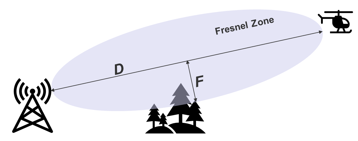
Fig. 5 - Illustration of Fresnel Zone Clearance
The Fresnel zone size increases with distance. The mid-point of the link has the biggest Fresnel zone. Another important factor is operating frequency. Lower frequency results in larger Fresnel zone and vice versa. Generally speaking, any more than 60% obstruction of the Fresnel zone will adversely affect the link distance. We've included a reference chart that gives an idea of the size of the 60% clearance required based on distance and frequency.
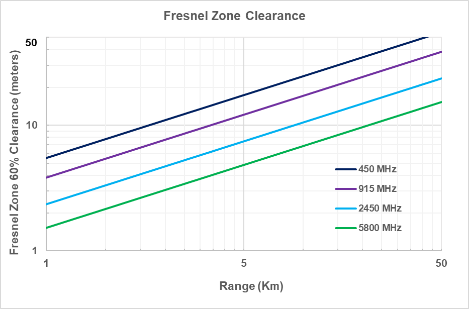
Fig. 6 - Fresnel Zone Clearance for different Frequencies
When designing the RF link for mobile nodes, it is important to consider the potential for Fresnel zone obstruction at all locations.
Our recommendation is to install antennas as high as possible to overcome the Fresnel zone obstruction and increase range.
Multipath fading and MCS rates
In applications where there are multiple propagation paths between a transmitter and receiver, replicas of the signal will arrive at different times with different amplitude and phase. This is especially important in ground applications, in built-up locations, over choppy water (sea water is highly reflective), or in areas with uneven terrain. This multipath propagation causes distortion to the signal which makes it more difficult to demodulate. When the radio reports RSSI (recevied signal strength indication), it reports the raw signal strength and not the quality of the signal. In such environments, you may find that the radio is using a much lower MCS rate than you would expect given the RSSI.
In mobile applications or environments which are rapidly changing (choppy sea water), the path loss and the nature of the signal distortion is constantly changing. It is the job of the radio's rate control algorithm to try and keep up with the changing link. Fig. 7 is an illustration of what real path loss may look like.
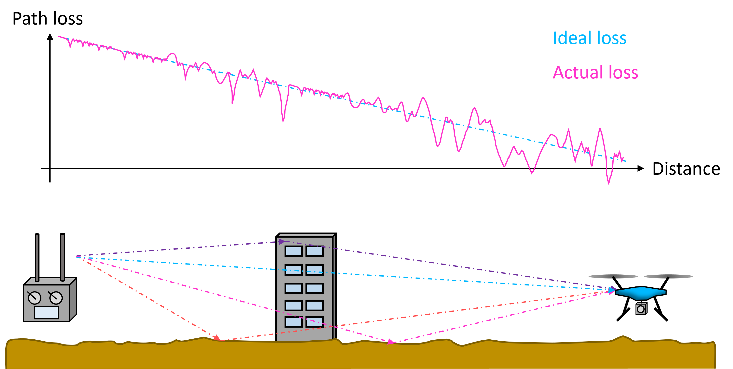
Fig. 7 - Illustration of multipath pass loss
The MCS rate determines the link speed at which data is sent over the wireless medium. For the same 1500 byte packet, a low MCS rate such as MCS0 will result in better sensitivity (and hence longer range), and better immunity to continuous noise. However, a low MCS rate also results in a longer frame duration in the air, which makes the packet more susceptible to being corrupted by bursts of interference.
- MCS0-7 are spatial diversity rates with modulation rates between 1/2-coded BPSK and 5/6-coded 64-QAM. The same packet is transmitted redundantly over both antennas. The radios use a technique called cyclic-shift-diversity to prevent unintentional beamforming.
- MCS8-15 are spatial multiplexing rates with the same modulation rates as MCS0-7. In this case, different packets are transmitted over each antenna allowing for double the link speed.
Spatial diversity rates are more robust to changes in the RF path, while spatial multiplexing rates offer higher link-speed. The radio automatically selects the best MCS rate through an interative trial and error process.
For mobile applications with real-time streaming requirements, we recommend enabling "Diversity Rates Only".
Configuring MCS and Diversity Rates
Diversity Rates Only can be enabled by navigating to network configuration -> traffic prioritization and selecting Optimize for Robustness (this was previously labelled Diversity Rates Only) and then clicking Save & Apply. Fig. 8 shows the Traffic Prioritization menu.
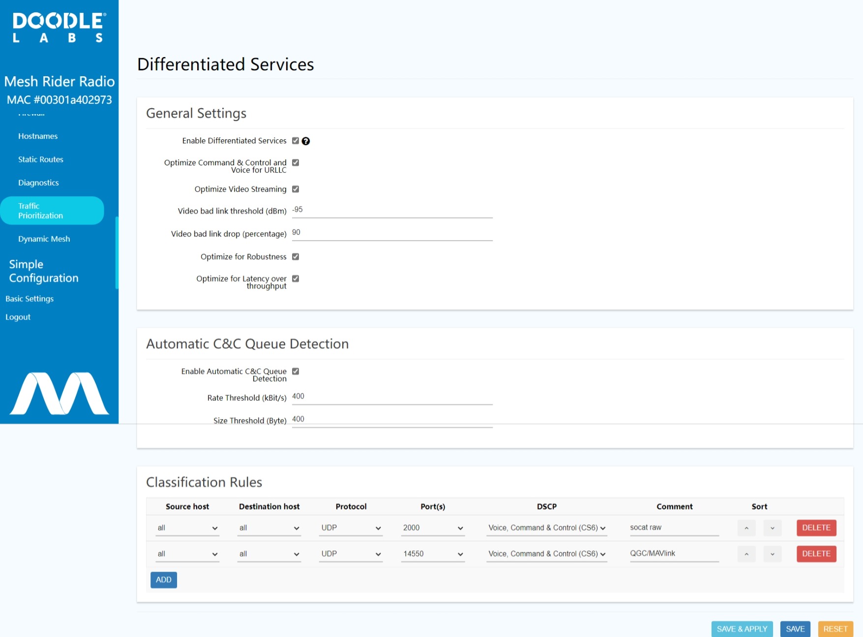
Fig. 8 Traffic Prioritization menu
You can also do this over the command line by using the commands
uci set diffserv.@general[0].diversity_rates='1'
uci commit
/etc/init.d/diffserv restart
wifi
Note that after enabling Diversity Rates Only, you can actually change the MCS rate to anything you want (including spatial multiplexing rates) by running
PHY=$(/usr/share/simpleconfig/get_fes_phy.sh)
uci set wireless.radio0.enabled_minstrel_mcs='0 5 6 7 13 15'
uci commit
wifi
In this case, we enabled MCS rates 0 5 6 7 13 15. If you only want to perform a short-term change to the MCS rate which will not survive a reboot, you can run
iw phy phy${PHY} set bitrates ht-mcs-2.4 <RATE>
To revert to automatic rate selection, run iw phy phy${PHY} set bitrates. Note that for C-Band radios where PHY==1, you will need to use ht-mcs-5 instead of ht-mcs-2.4.
Fade Margin
Fade margin is the allowable fluctuation in received signal strength while still maintaining the required performance. The higher the fade margin, the more reliable the link will be. Mesh Rider Radio receive sensitivities are listed on each model's datasheet. Maintaining a sufficient fade margin will create a buffer to account for natural fluctuation of the signal strength during operation. A fade margin of 10-15 dBm is a conservative value to target.
Our recommendation is to design a link with about 10-15 dB fade margin.
Noise and Interference
Noise and Interference are unwanted disturbances picked up by the radio which affect the receiver signal-to-noise ratio. Different disturbances affect the radio differently, and Mesh Rider radios use a combination of different techniques to provide the best overall solution. Consider the following different types of noise/interference
- a constant background hum often seen in urban environments in ISM bands where many radios are operating and spread out in the same vicinity.
- Mesh Rider radios are based on high-end industrial grade Qualcomm Wi-Fi chipsets whose receivers can demodulate signals with best-in-class sensitivity.
- high-level out-of-band interference due to a nearby cell tower.
- Mesh Rider radios are shielded at the critical parts of the RF path, and use highly selective RX filtering to attenuate out-of-band signals.
- intermittent high-level spikes of noise caused by a nearby transmitter.
- Mesh Rider radios use techniques including OFDM and spatial diversity allow them to operate in harsh RF environments.
These different types of interference and others are all handled using state-of-the art techniques in Mesh Rider radios.
LTE Desensitization
The Mesh Rider Radio includes highly selective RX filtering which allows it to operate in close proximity to high power LTE towers. That said, the EIRP of an LTE tower can exceed 1,000W (60 dBm) in some cases making coexistence a challenge. We recommend careful consideration of the LTE networks operating in the deployment area when designing your network.
The typical desensitization level of a 2.2-GHz Mesh Rider Radio (RM-2250) due to an out-of-band OFDM blocker is -8 dBm. As an example, assume the following parameters
- Base Station EIRP = 60 dBm
- LTE Band = 1
- Downlink frequency = 2140 MHz
- Mesh Rider Radio antenna gain = 3 dBi
In this case, the Mesh Rider Radio and LTE Base Station can be as close as 40m.
Automatic Channel and Band Selection (Sense)
Doodle Labs' Mesh Rider Radios include Sense, which is an intelligent protocol that detects the link quality and automatically moves the radios to a different operating frequency when the link quality is bad. More information is available here.
Throughput and Latency
Due to the use of ARQ, the network capacity is affected by the size of the frames going over the air. Increasing the frame size can result in significantly higher throughput, but also leads to increased latency. As of the September 2023 Sense release, there is a checkbox in the Traffic Prioritization settings labelled Optimize for Latency over Throughput. Enabling it results in improved latency, but the maximum achievable throughput is reduced by approximately half for high MCS rates. You can also enable it over the CLI using the following commands.
uci set diffserv.@general[0].diffserv.@general[0].low_latency='1'
uci commit
/etc/init.d/diffserv restart
wifi
Mesh Relay Nodes
It should be noted that the Mesh relay feature of the Mesh Rider Radio can help increase the range further, even for Non-Line of Sight (NLOS) conditions. Mesh Rider Radios support dual band mesh operation also to further extend this functionality.
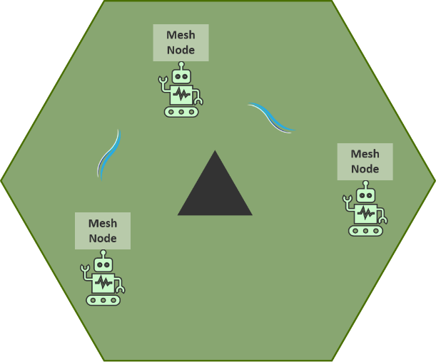
Fig. 9 - Mesh Relay Nodes
Conclusion
Our overall recommendation is to design the RF link with about 10-15 dB fade margin to account for changes in the environmental and operational conditions. Changes in orientation of mobile nodes can affect the link margin. Use the highest gain antenna possible within the physical constraints of the system. The objective is to operate the link with the highest SNR (RSSI) possible (the sweet spot for Mesh Rider Radio is around -40 dBm to -70 dBm RSSI). A higher RSSI level will allow the link to operate at the highest modulation, and provide the best throughput, interference resistance and reliability.