Mesh Rider Radio Wearable – Connector Descriptions
Overview
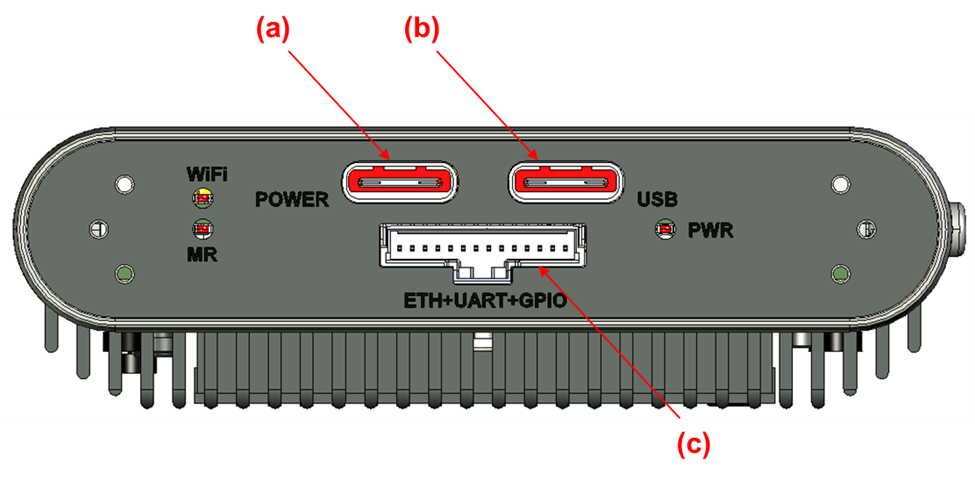
Fig. 1 Wearable Mesh Rider Radio Electrical Interfaces
- Power Connector (USB-C) - USB-PD compliant, 6-24V
- USB Device + Power Connector (USB-C) - 4.5v to 5.5v
- Auxiliary Connector (Molex 5015681407)
USB-C Connectors
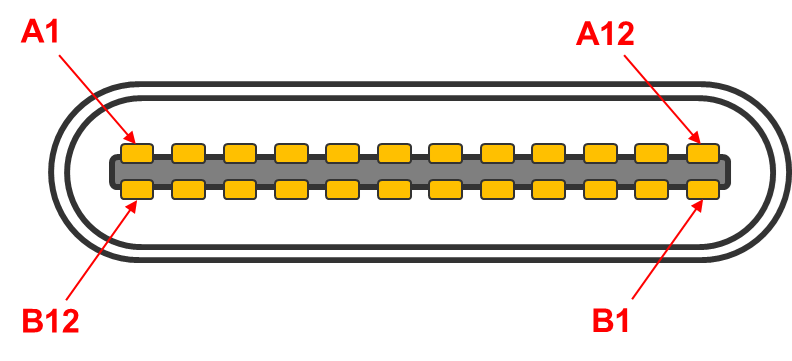
Fig. 2 USB-C Pin Numbering
Power Connector (a)
| Pin Number | Direction | Voltage | Pin Description |
|---|---|---|---|
| A1, B1 | - | GND | GND |
| A4, B4 | - | +6V - +24V | Power. 6-24 V. USB-PD Compliant. |
| A5 | I/O | 0V - +5V | CC1. Required for USB-PD. DO NOT USE |
| B5 | I/O | 0V - +5V | CC2. Required for USB-PD. DO NOT USE |
| A9, B9 | - | +6V - +24V | Power. 6-24 V. USB-PD Compliant. |
| A12, B12 | - | GND | GND |
| A2, B2, A3, B3, A6, B6, A7, B7, A8, B8, A10, B10, A11, B11 | - | - | No Internal Connection |
Data + Power Connector (USB-C Slave) (b)
| Pin Number | Direction | Voltage | Pin Description |
|---|---|---|---|
| A1, B1 | - | GND | GND |
| A4, B4 | - | +5V 5-V Input | |
| A6, B6 | I/O | Diff signal | USB_D+. USB Slave port which supports Ethernet over USB only. |
| A7, B7 | I/O | Diff signal | USB_D-. USB Slave port which supports Ethernet over USB only. |
| A9, B9 | - | +5V | 5-V Input |
| A12, B12 | - | GND | GND |
| A2, B2, A3, B3, A5, B5, A8, B8, A10, B10, A11, B11 | - | - | No Internal Connection |
Auxiliary Connector
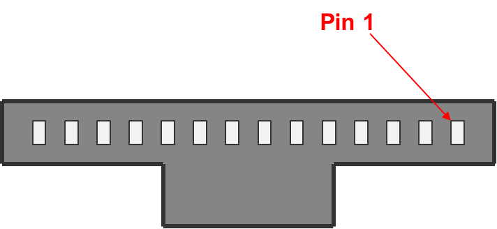
Fig. 3 Auxiliary Connector Pin Numbering. View from the front panel of the Wearable Mesh Rider Radio.
Auxiliary Connector (c)
| Pin Number | Direction | Voltage | Pin Description |
|---|---|---|---|
| 1 | O | +5-V | 5-V, 1A Output |
| 2 | I/O | Diff signal | USB_D-. USB Host port. Must be twisted with GND |
| 3 | I/O | Diff signal | USB_D+. USB Host port. Must be twisted with GND |
| 4 | O | Diff Signal | ETH1_TX- |
| 5 | O | Diff Signal | ETH1_TX+ |
| 6 | I | Diff Signal | ETH1_RX- |
| 7 | I | Diff Signal | ETH1_RX+ |
| 8 | - | - | N.C. |
| 9 | I | 0V - +VIN V | Power ON signal. Connected to a power push button. Peak voltage is equal to VIN which is rated up to 20 V. |
| 10 | - | GND | GND |
| 11 | I/O | 0V - +3.3 V | GPIO1 |
| 12 | O | 0V - +3.3 V | UART_TX |
| 13 | I | 0V - +3.3 V | UART_RX |
| 14 | - | GND | GND |