General Configuration
As discussed in the Getting Started guide, your initial configuration should use the Simple Configuration menu. This guide discusses how to tweak settings after applying your initial configuration. By default, the Simple Configuration only presents a small subset of all the possible configuration options of the Mesh Rider Radio. For further configuration, click the Advanced Settings button at the bottom left hand corner of the page.
Wireless Settings
The radio's Mesh Rider wireless settings can be found by navigating to Network -> Wireless in the GUI. This is where you can configure the Mesh Rider wireless interface. The Wearable (and OEM) variants have an additional WiFi radio which is also configured here, and the Helix variant's band switching is also configured here. These are discussed in the next section.
Mesh Rider Radio
To modify the wireless settings of the Mesh Rider radio, click Edit next to the relevant radio interface. You should see a page similar to the one below. We recommend the following updates.
- For point-to-point networks such as a Control Station controlling a single UAV, or Robot, Enable Dynamically Adjust txpower based on neighbor sounding (Transmit Power Control).
- At power up, the Mesh Rider Radio will scan the environment and choose the best channel for the environment. A different channel can be chosen manually.
- For 2.4-GHz ISM-band radios, avoid using a channel bandwidth of 20-MHz to avoid normal WiFi interference.
- Change the Mesh ID and under Wireless Security, change the password.
- Do NOT change the Mode of operation. This should be pre-selected in the Simple Configuration menu.
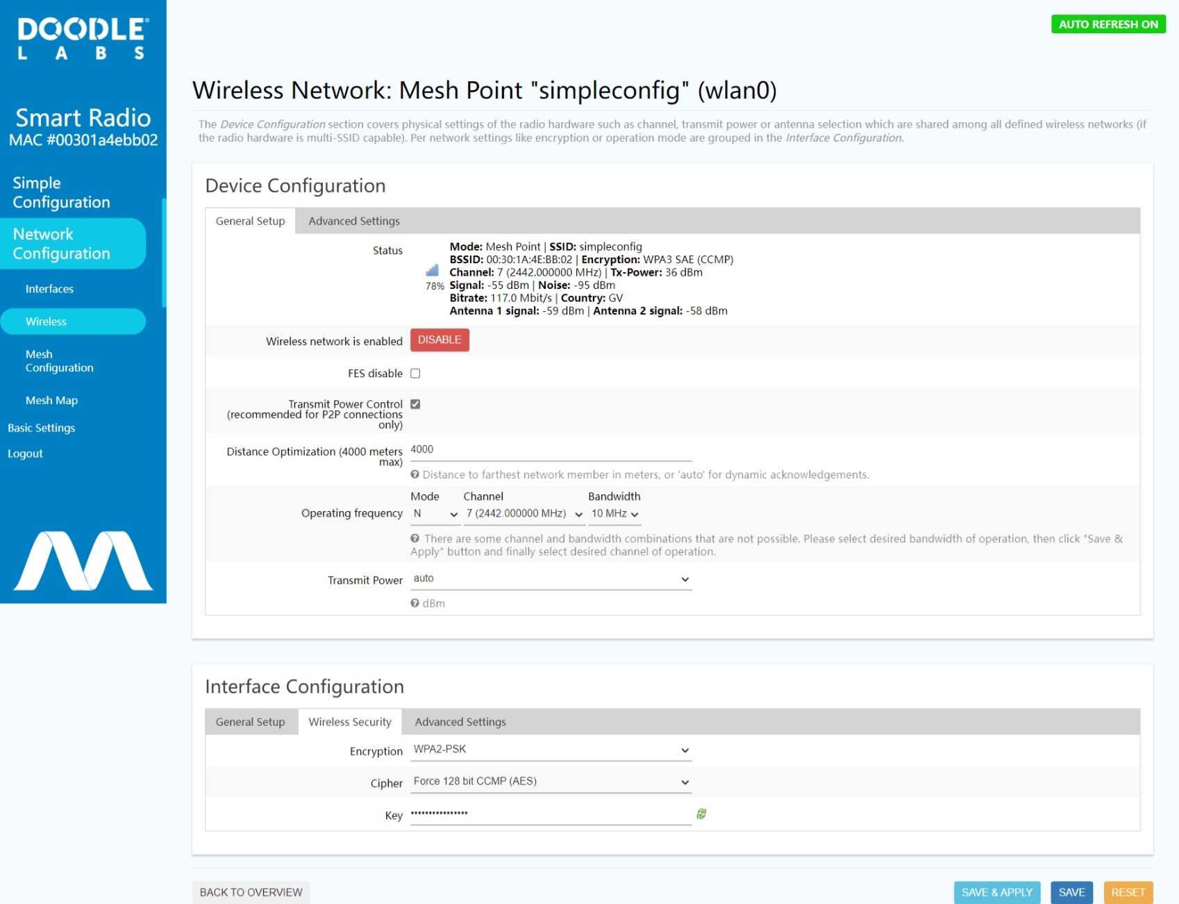
Fig. 1 Wireless Settings
Network Interface Settings
Network interface settings can be modified in the Network -> Interfaces tab. Below are some common changes you may want to make.
- Enable a DHCP server on one of the radios.
-Click
Editnext to theWANinterface. You should see a page similar to the picture below. Change theProtocolfromDHCPtoStatic Address. Add an IPv4 address and netmask of your choosing, then scroll to the bottom of the page, and un-checkDisable DHCP for this Interface. ClickSave & Apply. - Change the default static IP address of
ETH0. To do this, edit theWAN2interface, and change the static IP address to your liking.
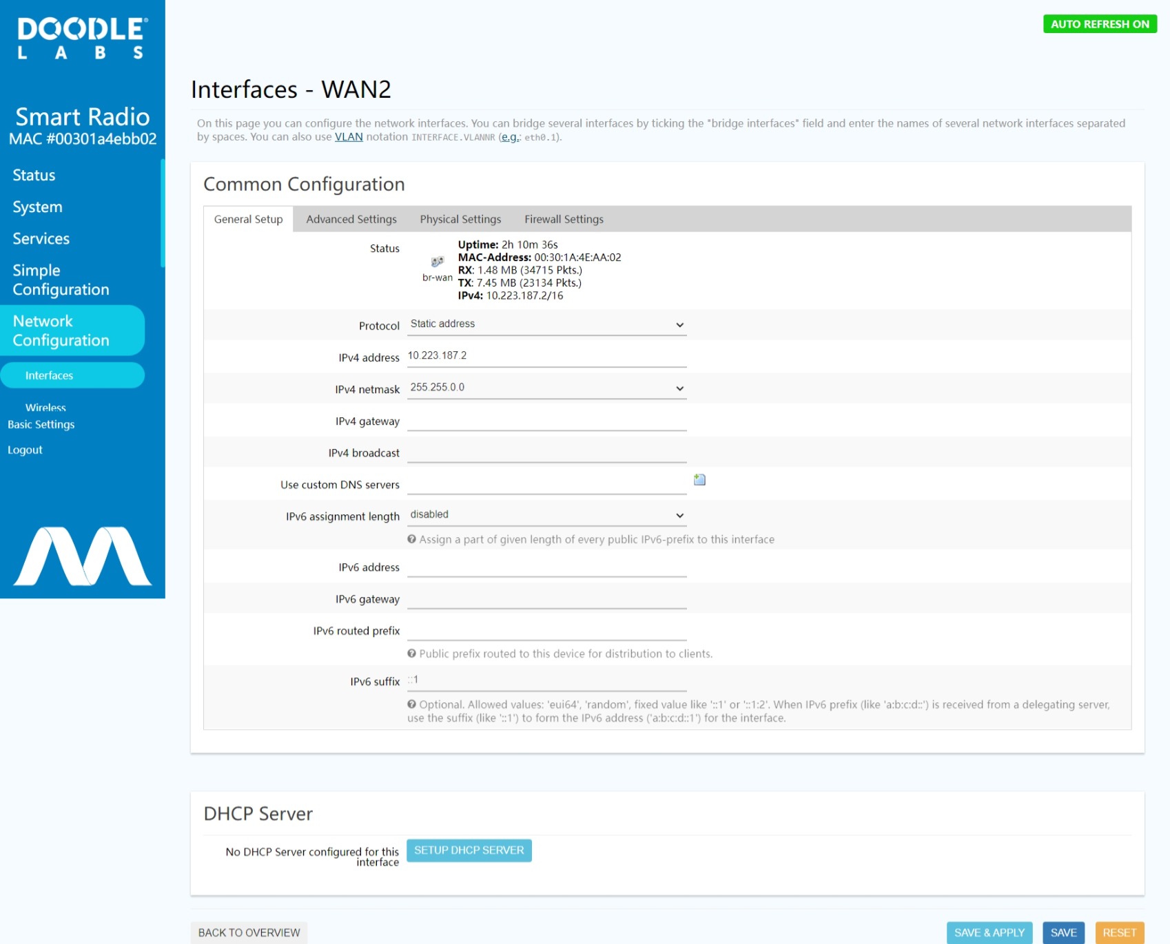
Fig. 2 Network Interface Settings
Mesh Settings
The default radio network configuration is a mesh, and the configuration settings can be accessed at Network -> Mesh Configuration. However, this menu is only accessible in the Advanced Settings which is opened by clocking the Advanced Settings button in the bottom of the left hand side menu bar. Fig. 3 shows the Mesh Configuration Page.
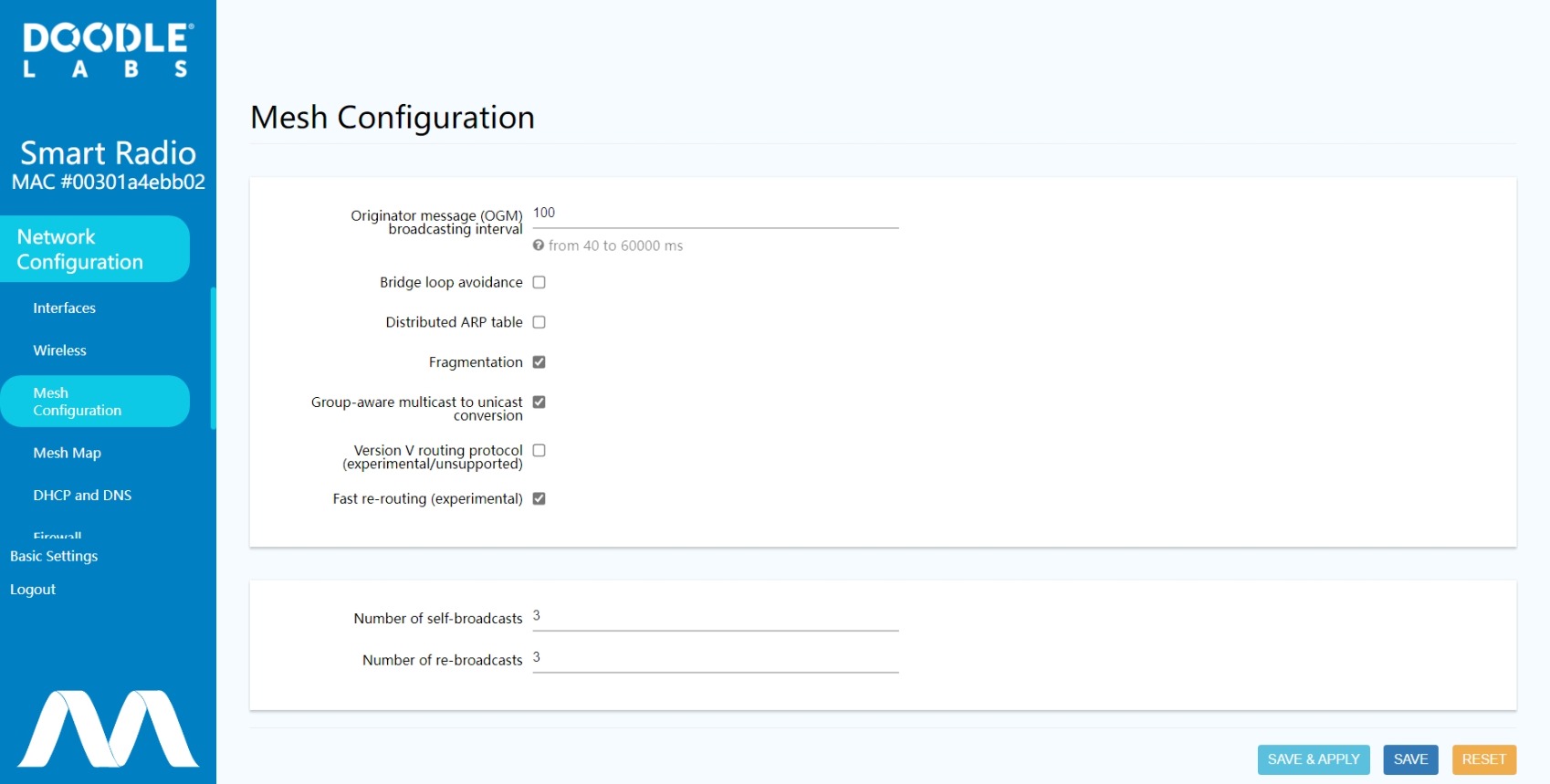
Fig. 3 Mesh Configuration Page
- OGM Broadcasting Interval: The radios send regular OGM broadcast packets to optimize mesh routing. Increasing the OGM interval makes the mesh less dynamic but consumes less resources. You may wish to increase the OGM broadcasting interval if your mesh exceeds 10 nodes.
- Bridge Loop Avoidance: Enable this option if your network includes broadcast loops formed externally to the Mesh Rider Radio mesh. e.g. a wired backbone connecting two mesh nodes.
- Distributed ARP table: Enable this option if you have a very widely distributed mesh (multiple hops).
- Fragmentation: The mesh layer will fragment packets which are larger than the radio interface's MTU. Generally this is not required, but the impact is minimal, so we recommend leaving it enabled.
- Group-aware multicast to unicast conversion: Converts all multicast traffic to unicast traffic. Not recommended for large swarms (e.g. more than 10 nodes) which rely on multicasting small low-rate packets to a large number of listeners.
- Version V routing protocol: For experimentation only. Uses a throughput-based metric for mesh routing decisions.
- Fast re-routing: Recommended for most mesh setups. Not recommended when a reliable broadcast link is required at long range.
- Number of self-broadcasts: The number of times broadcast packets which are generated by the radio are transmitted.
- Number of re-broadcasts: The number of times broadcast packets which originated from another host are re-broadcast.
Traffic Prioritization and Link Optimization
Different types of traffic can be prioritized in the Traffic Prioritization menu. This is useful when operating in a crowded wireless medium. There are four different queues - Voice, Video, Best Effort, and Background. The Voice queue optimizes latency and may also be used for command and control, the Video queue optimizes throughput, the Best Effort Queue is essentially unoptimized, and the Background queue is for low-priority data.
To use these QoS features, open up the web GUI and navigate to Network -> Traffic Prioritization. The Mesh Rider Radio includes software to map different network protocols or ports to the various QoS queues. To do so, click Enable Differentiated Services, and add a classification rule to suit the application's needs. For example, you can send all UDP traffic to the Video queue which is beneficial for video transmission.
URLLC (Ultra Reliable Low Latency Channel) and Video Optimization
The Mesh Rider Radio includes protocol optimizations for URLLC applications as well as video optimizations. URLLC applications typically include command and control (C&C) data but can be extended to any application requiring a reliable low latency. Let's assume that we have a C&C application which uses network port 7000 over UDP. In the screenshot below, first click Optimize Command & Control for URLLC. Next click Add, and then change the new classification rule to use Port 7000 and set the DSCP value to CS6. The comment section can be filled in if desired. Finally click Save & Apply and wait for the page to refresh.
Note that if the application uses a large number of telemetry streams, or if the data-rate going over the URLLC channel is too large, then enabling URLLC may actually be detrimental to the performance.
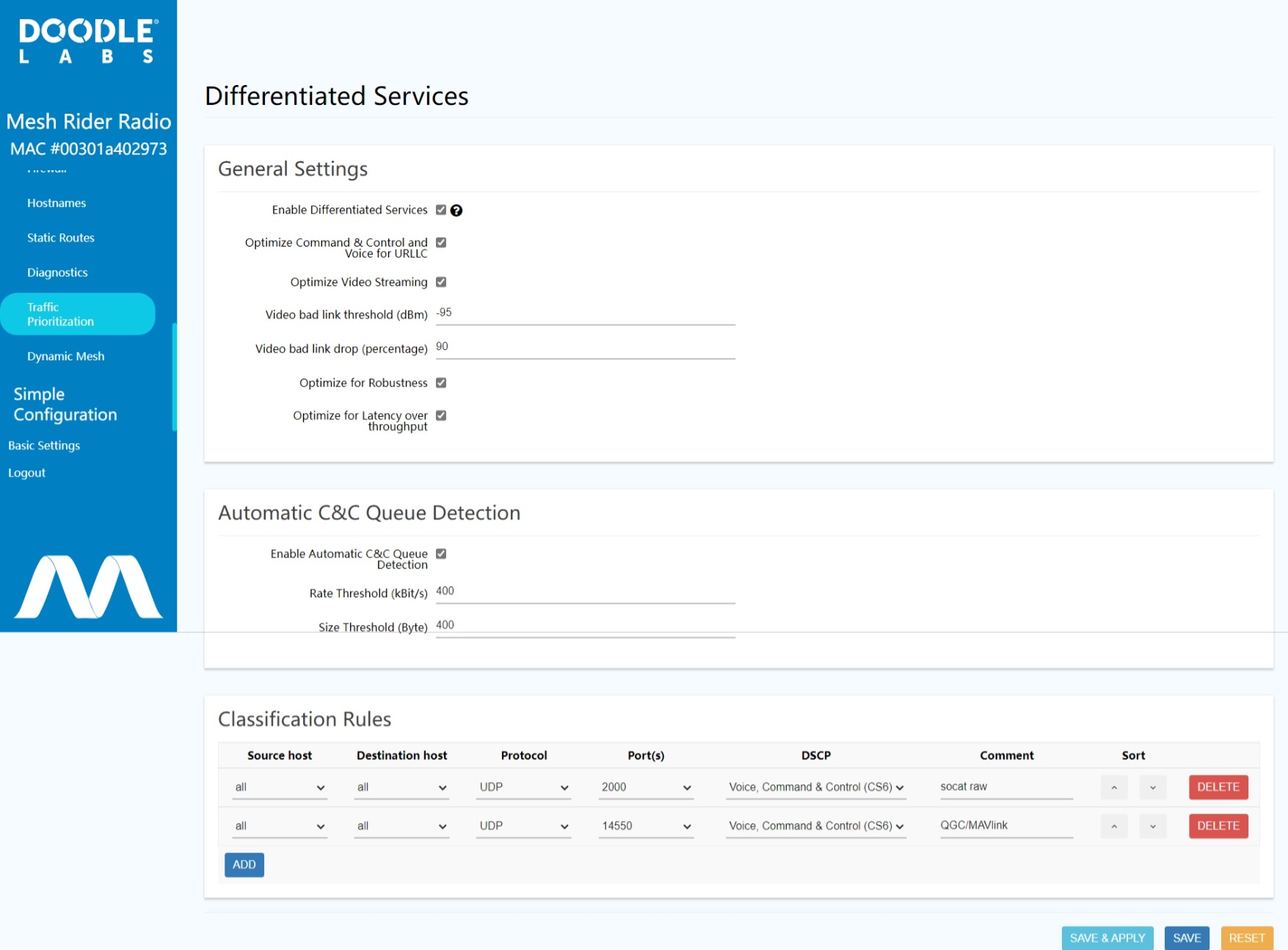
Fig. 4 Traffic Prioritization Settings
If Optimize Video Streaming is enabled, the radio will
- Apply radio PHY settings which are optimized for video transmission
- If the RSSI to a particular station is below the
Video bad link threshold, then the radio will dropVideo bad link (percentage)packets. This is an optional feature, and you should adjust the RSSI to a reasonable value for your application.
The RSSI bad-link threshold is an additional protection against network overload when the link quality is bad, but even without setting the RSSI bad-link threshold, the C&C queue is prioritized over the VI queue.
Latency, Throughput, and Robustness Optimization
The Sept 2023 Sense release firmware includes two new checkboxes. The Optimize for Robustness checkbox replaces the Diversity Rates Only checkbox in older firmware. This forces the radio to send the same data over both antennas redundantly which leads to smoother performance in highly dynamically changing conditions (e.g. UAVs, UGVs). Note that it also reduces the maximum achievable throughput by 50%.
The Optimize for Latency over Throughput does what the name implies. It results in improved latency, but the maximum achievable throughput is reduced by approximately half for high MCS rates.
Both of these settings are recommended for mobile robotics applications where low latency, smooth realtime video and C&C are required.
Further Link Optimization
Further Link Optimization is discussed in our RF Link Optimization document.
Firewall Settings
The Firewall configuration is located under Network -> Firewall and can be modified over the GUI and CLI at /etc/config/firewall.
We shall use the iperf3 application as an example to demonstrate setting a firewall rule to allow access to port 5201 of the router. Navigate to the Firewall page, and click the Traffic Rules tab. In the Open ports on router section, enter the name, protocol, and port number as Allow iperf, TCP, and 5201 respectively so that clients are able to connect to port 5201.
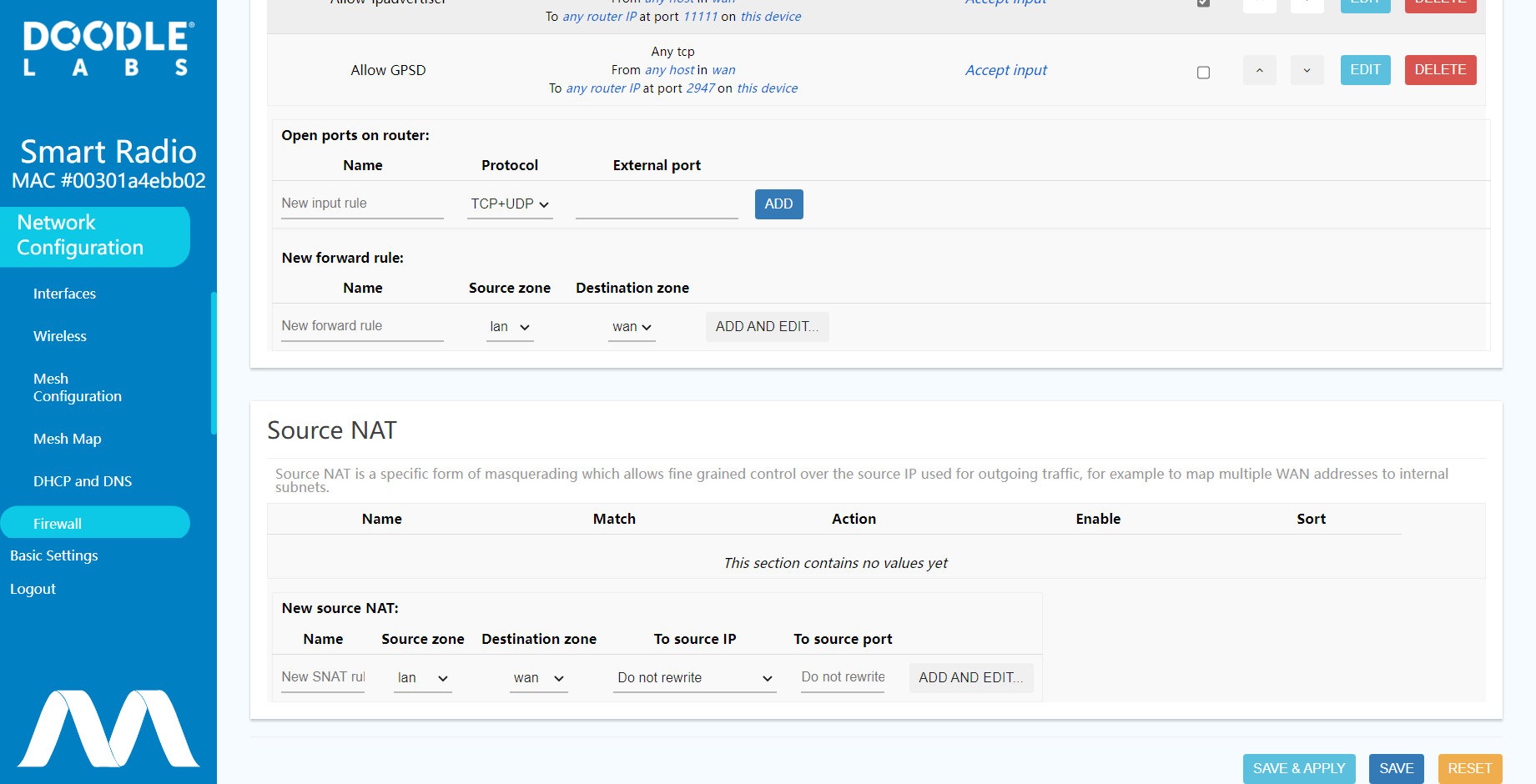
Fig. 5 Firewall Settings
Before port 5201 is opened, run iperf in server mode inside the Mesh Rider Radio.
root@smartradio:~# iperf3 -s
If you try and connect to the iperf server from your local machine, you will get an error, connect failed: Connection refused. After opening the firewall at port 5201, you should be able to connect to the iperf3 server.
Extensive information regarding Firewall configuration is available at the http://openwrt.org website.