External Mesh Rider Radio (-J) and Embedded EVK Connector Descriptions
Overview
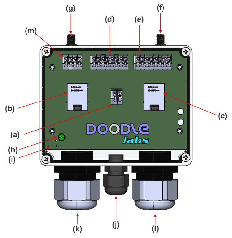
Fig. 1a External Mesh Rider Radio (-J) Electrical Interfaces
- Power Connector
- Standard RJ45 ETH0
- Standard RJ45 ETH1
- AUX1 Connector
- AUX2 Connector
- Standard SMA Connector (ANT1)
- Standard SMA Connector (ANT0)
- Power LED
- Reset Button
- PWR Cable Gland
- ETH0 Cable Gland
- ETH1 Cable Gland
- not populated
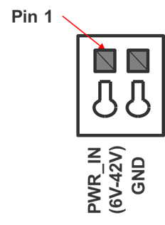
Power Connector (a)
Fig. 2 Power Connector Pin Numbering
Power Connector (a)
| Pin Number |
Direction |
Voltage |
Pin Description |
| 1 |
- |
+6 V – +42 V |
PWR |
| 2 |
- |
- |
GND |
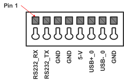
AUX1 Connector (d)
Fig. 3 AUX1 Pin Numbering
AUX1 Connector (d)
| Pin Number |
Direction |
Voltage |
Pin Description |
| 1 |
I |
-12 V - +12 V |
RS232_RX |
| 2 |
O |
-12 V - +12 V |
RS232_TX |
| 3 |
- |
GND |
GND |
| 4 |
- |
GND |
GND |
| 5 |
O |
+5 V |
+5 V Output from Mesh Rider Radio |
| 6 |
I/O |
Diff Signal |
USB0_DP |
| 7 |
I/O |
Diff Signal |
USB0_DN |
| 8 |
- |
GND |
GND |
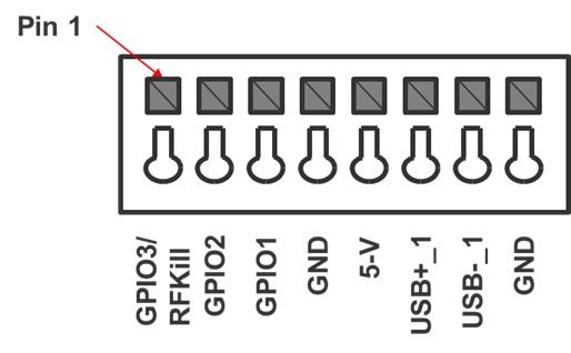
AUX2 Connector (e)
Fig. 4 AUX2 Pin Numbering
AUX2 Connector (e)
| Pin Number |
Direction |
Voltage |
Pin Description |
| 1 |
I/O |
+3 V |
GPIO3/RFKill |
| 2 |
I/O |
+3 V |
GPIO2 |
| 3 |
I/O |
+3 V |
GPIO1 |
| 4 |
- |
GND |
GND |
| 5 |
O |
+5 V |
+5 V Output from Mesh Rider Radio |
| 6 |
I/O |
Diff Signal |
USB1_DP |
| 7 |
I/O |
Diff Signal |
USB1_DN |
| 8 |
- |
GND |
GND |
Embedded Mesh Rider Radio Evaluation Kit
The Embedded Mesh Rider Radio Evaluation Kit uses the same PCB as the External Radio with the following important changes.
- In Fig. 1, (i) the reset button is not connected to the Mesh Rider Radio. Use the pin-hole reset on the Mesh Rider Radio instead.
- In the AUX1 Connector (d), pins 1 and 2 use 0V - +3.3V TTL signalling levels instead of RS232.